12
Test Procedures
ELECTRIC VEHICLE - ELECTRICAL SYSTEM
TROUBLESHOOTING
9.
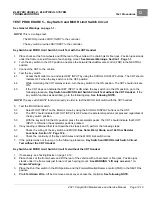
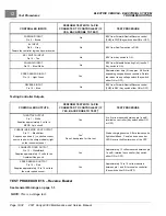
Place the Run/Tow switch in the RUN position, turn the key switch to the ON position, place the Forward/Reverse
rocker switch in the F position, and press the accelerator pedal. The rear tire should rotate and the multimeter
should show a change in resistance. If not, replace the solenoid.
See Solenoid Removal on page 13-6.
TEST PROCEDURE 10 – Charger Interlock
See General Warnings on page 1-1.
Controller Interlock Function Test with the CDT Handset
1.
If necessary, see Testing Basics on page 12-12.
2.
Connect the CDT to the vehicle.
3.
Access the Monitor menu and select CHARGER INHIBIT by using the SCROLL DISPLAY buttons. The CDT
should indicate OFF.
4.
For external charger:
Insert the charger DC cord into the vehicle's charger receptacle.
For onboard charger:
Insert the onboard charger AC plug into an AC outlet.
5.
In a few seconds, the CDT should indicate ON and the vehicle can no longer be driven. If not, check the KEY,
FORWARD, REVERSE and FOOT INPUTS to the controller.
– If the CDT does not indicate ON, check circuit wiring and DC plug connection. See the following procedure
Testing the Interlock Circuit
.
– If the CDT does indicate ON, but the vehicle can still be driven, replace the controller.
Removal, Section 13, Page 13-7.
Testing the Interlock Circuit
The charger interlock circuit consists of a 48 V power source through the RUN/TOW switch, a diode, a 10k ohm
resistor, the charger receptacle blue wire and DC plug.
See following NOTE.
Use the following procedure to test the
charger interlock circuit:
NOTE:
The following steps involve testing voltage and resistance.
At the charger end of the DC cord, the black wire and blue wire are crimped together in the same fork terminal.
This closes the circuit once the DC cord plug is inserted into the charger receptacle.
1.
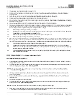
With batteries connected, place the Run/Tow switch in the RUN position.
2.
Remove electronics module cover.
See Electric Vehicle - Electrical Components, Section 13, Page 13-1.
3.
Check 15-amp fuse: See Test Procedure 4 – Fuses on page 12-16.
4.
Check power:
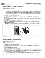
Using a multimeter set to 200- volts DC, place red (+) probe (with insulation-piercing probe) on the
light blue wire (pin 5 of the 16-pin connector) and black (–) probe on B- terminal of controller. The reading should
be approximately 42 to 46 volts. If the reading is not approximately 42 to 46- volts, go to check the 10k ohm
resistor. If the reading is approximately 42 to 46 volts, check continuity of circuit wires.
5.
Check 10k ohm resistor:
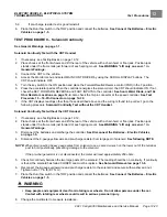
Set multimeter to 20k ohms. Remove the 15-amp fuse. With the red (+) probe (with
insulation-piercing probe) still on the light blue wire (pin 5 of the 16-pin connector), place the black (–) probe to the
red wire terminal in the 15-amp fuse holder. The reading should be approximately 10.0k ohms. If the reading is
not approximately 10.0k ohms, replace the resistor or main wire harness
6.
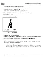
Check continuity:
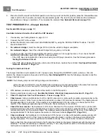
Set multimeter to Continuity test. With the red (+) probe (with insulation-piercing probe) still
on the light blue wire (pin 5 of the 16-pin connector), place the black (–) probe in the blue wire terminal of the
charger receptacle. The meter should beep to indicate continuity. If not, check bullet connector of blue wires.
Next, probe from the pink wire terminal in the 15-amp fuse holder to the large solenoid post with the red wires
attached. The meter should beep to indicate continuity. If not, verify Run/Tow switch is in RUN and check the
red-to-pink wire spade connector near the solenoid.
Page 12-24
2021 Carryall 300 Maintenance and Service Manual
Summary of Contents for Carryall 300 2021
Page 2: ......
Page 16: ......
Page 551: ...80 2018 by Kohler Co All rights reserved KohlerEngines com 17 690 15 Rev...
Page 565: ...GASOLINE ENGINE HARNESS Wiring Diagrams Gasoline Engine Harness 26...
Page 566: ...Page intentionally left blank...
Page 567: ...GASOLINE KEY START MAIN HARNESS Wiring Diagrams Gasoline Key Start Main Harness 26...
Page 568: ...Page intentionally left blank...
Page 569: ...GASOLINE PEDAL START MAIN HARNESS Wiring Diagrams Gasoline Pedal Start Main Harness 26...
Page 570: ...Page intentionally left blank...
Page 571: ...GASOLINE INSTRUMENT PANEL HARNESS Wiring Diagrams Gasoline Instrument Panel Harness 26...
Page 572: ...Page intentionally left blank...
Page 573: ...GASOLINE FNR HARNESS Wiring Diagrams Gasoline FNR Harness 26...
Page 574: ...Page intentionally left blank...
Page 575: ...ELECTRIC MAIN HARNESS Wiring Diagrams Electric Main Harness 26...
Page 576: ...Page intentionally left blank...
Page 577: ...ELECTRIC INSTRUMENT PANEL HARNESS Wiring Diagrams Electric Instrument Panel Harness 26...
Page 578: ...Page intentionally left blank...
Page 579: ...ELECTRIC ACCESSORIES HARNESS Wiring Diagrams Electric Accessories Harness 26...
Page 580: ...Page intentionally left blank...
Page 588: ...NOTES...
Page 589: ...NOTES...
Page 590: ...NOTES...
Page 591: ...NOTES...
Page 592: ...NOTES...
Page 593: ...NOTES...
Page 594: ...NOTES...
Page 595: ......
Page 596: ......

