


12
Test Procedures
ELECTRIC VEHICLE - ELECTRICAL SYSTEM
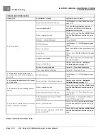
TROUBLESHOOTING
If no voltage is coming to the Run/Tow Switch, inspect the red-to-pink wire spade connection at the solenoid.
Run/Tow Switch Test with the CDT Handset
1.
With the Run/Tow switch in the RUN position, connect the CDT to the vehicle.
2.
Immediately after the CDT is connected to the vehicle, the screen should display a copyright notice and the
CDT model number.
3.
If the CDT display screen remains blank, the CDT port has failed. In this case, disconnect the CDT from the
port and connect it directly to the controller
4.
If the CDT display screen begins to work, go to step 5; otherwise, perform the following procedure,
Run/Tow
Switch Test without the CDT Handset
.
5.
With the CDT still connected to vehicle, place Run/Tow Switch in TOW position.
6.
If the CDT display screen goes blank, the Run/Tow switch and connecting wires are operating correctly.
7.
If the CDT display screen is still active, the switch has failed closed. Replace the Run/Tow switch.
Run/Tow Switch Test without the CDT Handset
WARNING
• The key switch should be placed in the OFF position and left in the OFF position for the duration
of this test.
1.
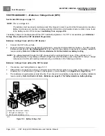
If necessary, see Testing Basics on page 12-12.
2.
Access the Run/Tow switch but do not disconnect wires.
3.
With the Run/Tow switch in the RUN position:
3.1.
The pink wire should show BPV coming to the switch.
3.2.
The light green wire should also show BPV. If it shows less than 5 volts, the switch has failed OPEN
and must be replaced.
4.
With the Run/Tow switch in the TOW position:
4.1.
The light green wire should show less than 5 volts. If it still shows BPV, the switch has failed CLOSED
and must be replaced.
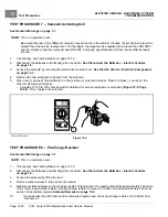
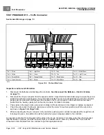
TEST PROCEDURE 4 – Fuses
See General Warnings on page 1-1.
WARNING
• Failure to use properly rated fuse can result in a fire hazard.
NOTE:
These vehicles predominately use a combination of ATC-style and ATM-style blade fuses. A single AGC-style
glass fuse is used for the charger interlock circuit.
This is a voltage test. It can be performed relatively easily on ATC-style and ATM-style fuses. A voltage
test can be performed on the AGC-style glass fuse if insulation-piercing probes are used. Otherwise, the
AGC-style will have to be removed to visually inspect or check using a continuity test.
Page 12-16
2021 Carryall 300 Maintenance and Service Manual
Summary of Contents for Carryall 300 2021
Page 2: ......
Page 16: ......
Page 551: ...80 2018 by Kohler Co All rights reserved KohlerEngines com 17 690 15 Rev...
Page 565: ...GASOLINE ENGINE HARNESS Wiring Diagrams Gasoline Engine Harness 26...
Page 566: ...Page intentionally left blank...
Page 567: ...GASOLINE KEY START MAIN HARNESS Wiring Diagrams Gasoline Key Start Main Harness 26...
Page 568: ...Page intentionally left blank...
Page 569: ...GASOLINE PEDAL START MAIN HARNESS Wiring Diagrams Gasoline Pedal Start Main Harness 26...
Page 570: ...Page intentionally left blank...
Page 571: ...GASOLINE INSTRUMENT PANEL HARNESS Wiring Diagrams Gasoline Instrument Panel Harness 26...
Page 572: ...Page intentionally left blank...
Page 573: ...GASOLINE FNR HARNESS Wiring Diagrams Gasoline FNR Harness 26...
Page 574: ...Page intentionally left blank...
Page 575: ...ELECTRIC MAIN HARNESS Wiring Diagrams Electric Main Harness 26...
Page 576: ...Page intentionally left blank...
Page 577: ...ELECTRIC INSTRUMENT PANEL HARNESS Wiring Diagrams Electric Instrument Panel Harness 26...
Page 578: ...Page intentionally left blank...
Page 579: ...ELECTRIC ACCESSORIES HARNESS Wiring Diagrams Electric Accessories Harness 26...
Page 580: ...Page intentionally left blank...
Page 588: ...NOTES...
Page 589: ...NOTES...
Page 590: ...NOTES...
Page 591: ...NOTES...
Page 592: ...NOTES...
Page 593: ...NOTES...
Page 594: ...NOTES...
Page 595: ......
Page 596: ......