


ELECTRIC VEHICLE - ELECTRICAL SYSTEM
TROUBLESHOOTING
Test Procedures
12
TEST PROCEDURE 2 – 48-Volt Battery Pack Voltage Under Load
See General Warnings on page 1-1.
NOTE:
This is a voltage test.
1.
If necessary, see Testing Basics on page 12-12.
2.
Be sure the batteries are fully charged and that the electrolyte level is correct in all cells.
3.
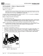
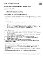
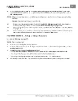
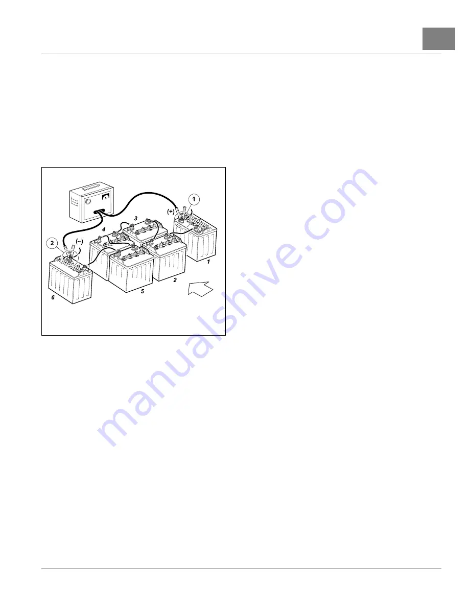
Connect the tester leads to the positive (+) post of battery no.1 and negative (–) post of battery no.6
TES
TER
(Viewed from driver side of vehicle)
1. RED probe to battery no. 1 (+).
2. BLACK probe to battery no. 6 (-).
2992
Figure 12-3
Battery Discharge Test
4.
Turn the discharge machine on and record the voltage reading of battery pack while under load.
5.
A fully charged set of batteries in good condition should read between 46 and 49 volts while under load.
6.
A reading of 32 to 46 volts indicates discharged or failed batteries. Each battery should be checked with a
multimeter while under load.
See following NOTE.
NOTE:
If a 48-volt set of batteries is down in the 32 to 38 volt range, the discharge machine will activate but it will
think it is testing a 36-volt battery set.
7.
A reading of 31.5 volts or less will not activate discharge machine. If the voltage of the batteries is below 32–
volts, the batteries are deeply discharged or have failed.
8.
Recording the battery pack voltage reading while under load provides a more accurate diagnosis of the condition
of the batteries. When the discharge machine is ON, it places the battery pack under load and many times
can help determine if one or more batteries in the set have failed. Testing battery voltage while the batteries
are not under load will not always indicate the true condition of the batteries. For more information about the
batteries, refer to 14
.
TEST PROCEDURE 3 – Run/Tow Switch
See General Warnings on page 1-1.
NOTE:
This is a voltage test.
2021 Carryall 300 Maintenance and Service Manual
Page 12-15
Summary of Contents for Carryall 300 2021
Page 2: ......
Page 16: ......
Page 551: ...80 2018 by Kohler Co All rights reserved KohlerEngines com 17 690 15 Rev...
Page 565: ...GASOLINE ENGINE HARNESS Wiring Diagrams Gasoline Engine Harness 26...
Page 566: ...Page intentionally left blank...
Page 567: ...GASOLINE KEY START MAIN HARNESS Wiring Diagrams Gasoline Key Start Main Harness 26...
Page 568: ...Page intentionally left blank...
Page 569: ...GASOLINE PEDAL START MAIN HARNESS Wiring Diagrams Gasoline Pedal Start Main Harness 26...
Page 570: ...Page intentionally left blank...
Page 571: ...GASOLINE INSTRUMENT PANEL HARNESS Wiring Diagrams Gasoline Instrument Panel Harness 26...
Page 572: ...Page intentionally left blank...
Page 573: ...GASOLINE FNR HARNESS Wiring Diagrams Gasoline FNR Harness 26...
Page 574: ...Page intentionally left blank...
Page 575: ...ELECTRIC MAIN HARNESS Wiring Diagrams Electric Main Harness 26...
Page 576: ...Page intentionally left blank...
Page 577: ...ELECTRIC INSTRUMENT PANEL HARNESS Wiring Diagrams Electric Instrument Panel Harness 26...
Page 578: ...Page intentionally left blank...
Page 579: ...ELECTRIC ACCESSORIES HARNESS Wiring Diagrams Electric Accessories Harness 26...
Page 580: ...Page intentionally left blank...
Page 588: ...NOTES...
Page 589: ...NOTES...
Page 590: ...NOTES...
Page 591: ...NOTES...
Page 592: ...NOTES...
Page 593: ...NOTES...
Page 594: ...NOTES...
Page 595: ......
Page 596: ......