


GASOLINE VEHICLE - TROUBLESHOOTING
AND ELECTRICAL SYSTEM
Test Procedures
18
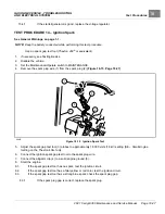
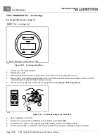
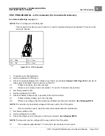
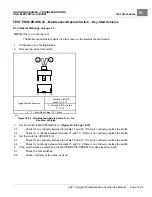
TEST PROCEDURE 26 – 4-Pin Connector (for Connected Car Device)
See General Warnings on page 1-1.
NOTE:
This is a voltage and continuity test.
The Connected Car Device 4-pin connector is used for Guardian/Visage and is labeled “V3 circuit” on the
main wire harness.
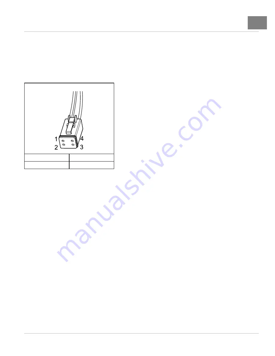
Pin 1 – Black
Pin 4 – Open
Pin 2 – Red
Pin 3 – Open
2786
Figure 18-26
4-Pin Connector
1.
If necessary, see Testing Basics.
2.
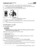
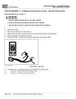
Set the multimeter to 200 Ohms.
3.
Check for continuity between pin 1 (black wire) of the 4-pin connector
and pin 18
(black wire) of the black 18-pin connector on the ECU.
3.1.
If there is continuity, go to the next step.
3.2.
If there is no coninuity, check sonic welds 4, 10, and 14. Proceed to the next step.
4.
Set the key switch to ON.
5.
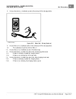
Set the multimeter to 20 VDC.
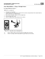
6.
Check for battery voltage at pin 2 (red wire) of the 4-pin connector.
6.1.
If there is battery voltage, go to the next step.
6.2.
If there is no voltage, check the 2-amp fuse located near the 4-pin connector.
See following NOTE.
NOTE:
The red wire only has battery voltage with the key switch in the ON position.
6.3.
If the 2-amp fuse is good, check the 5-amp fuse located near the electrical box.
7.
Set the key switch to ON.
8.
Set the multimeter to 20 VDC.
9.
Check the voltage at pin 4 (blue wire) of the 4-pin connector.
See following NOTE.
NOTE:
The blue wire only has voltage with the key switch in the ON position.
9.1.
If the voltage is approximately 11.8 volts, the 4-pin connector circuit is good.
2021 Carryall 300 Maintenance and Service Manual
Page 18-41
Summary of Contents for Carryall 300 2021
Page 2: ......
Page 16: ......
Page 551: ...80 2018 by Kohler Co All rights reserved KohlerEngines com 17 690 15 Rev...
Page 565: ...GASOLINE ENGINE HARNESS Wiring Diagrams Gasoline Engine Harness 26...
Page 566: ...Page intentionally left blank...
Page 567: ...GASOLINE KEY START MAIN HARNESS Wiring Diagrams Gasoline Key Start Main Harness 26...
Page 568: ...Page intentionally left blank...
Page 569: ...GASOLINE PEDAL START MAIN HARNESS Wiring Diagrams Gasoline Pedal Start Main Harness 26...
Page 570: ...Page intentionally left blank...
Page 571: ...GASOLINE INSTRUMENT PANEL HARNESS Wiring Diagrams Gasoline Instrument Panel Harness 26...
Page 572: ...Page intentionally left blank...
Page 573: ...GASOLINE FNR HARNESS Wiring Diagrams Gasoline FNR Harness 26...
Page 574: ...Page intentionally left blank...
Page 575: ...ELECTRIC MAIN HARNESS Wiring Diagrams Electric Main Harness 26...
Page 576: ...Page intentionally left blank...
Page 577: ...ELECTRIC INSTRUMENT PANEL HARNESS Wiring Diagrams Electric Instrument Panel Harness 26...
Page 578: ...Page intentionally left blank...
Page 579: ...ELECTRIC ACCESSORIES HARNESS Wiring Diagrams Electric Accessories Harness 26...
Page 580: ...Page intentionally left blank...
Page 588: ...NOTES...
Page 589: ...NOTES...
Page 590: ...NOTES...
Page 591: ...NOTES...
Page 592: ...NOTES...
Page 593: ...NOTES...
Page 594: ...NOTES...
Page 595: ......
Page 596: ......


