


ELECTRIC VEHICLE - ELECTRICAL SYSTEM
TROUBLESHOOTING
Test Procedures
12
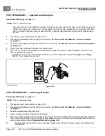
TEST PROCEDURE 5 – Key Switch and MCOR Limit Switch Circuit
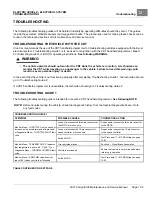
See General Warnings on page 1-1.
NOTE:
This is a voltage test.
The MCOR provides FOOT INPUT to the controller.
The key switch provides KEY INPUT to the controller.
Key Switch and MCOR Limit Switch Circuit Test with the CDT Handset
1.
Place chocks at the front wheels and lift the rear of the vehicle with a chain hoist or floor jack. Position jack stands
under the frame rails just forward of each spring mount.
See General Warnings, Section 1, Page 1-1.
2.
Turn the key switch to the OFF position and place the Forward/Neutral/Reverse control (FNR) in the NEUTRAL
position.
3.
Connect the CDT to the vehicle.
4.
Test the key switch.
4.1.
Access the Monitor menu and select KEY INPUT by using the SCROLL DISPLAY buttons. The CDT should
indicate OFF when the key switch is in the OFF position.
4.2.
While monitoring the CDT display screen, turn the key switch to the ON position. The CDT should indicate
ON.
4.3.
If the CDT does not indicate that KEY INPUT is ON when the key switch is in the ON position, go to the
following procedure,
Key Switch and MCOR Limit Switch Circuit Test without the CDT Handset
. If the
key switch functions as described, go to the following step.
See following NOTE.
NOTE:
The key switch MUST function properly in order to test the MCOR limit switch with the CDT handset.
5.
Test the MCOR limit switch.
5.1.
Select FOOT INPUT on the Monitor menu by using the SCROLL DISPLAY buttons on the CDT.
5.2.
The CDT should indicate that FOOT INPUT is OFF when the accelerator pedal is not pressed, regardless of
the key switch position.
5.3.
With the key switch in the ON position, press the accelerator pedal. The CDT should indicate that FOOT
INPUT is ON when the accelerator pedal is pressed.
6.
If any reading is obtained that is not described in steps 4 and 5, perform the following steps:
6.1.
Check the wiring of the key switch and MCOR.
See Sonic Weld, Diode, and 10k Ohm Resistor
Locations, Section 12, Page 12-4.
6.2.
Check the continuity of the key switch wires and the MCOR limit switch wires.
7.
If the problem was not found, go to the following procedure,
Key Switch and MCOR Limit Switch Circuit
Test without the CDT Handset
.
Key Switch and MCOR Limit Switch Circuit Test without the CDT Handset
1.
If necessary, see Testing Basics on page 12-12.
2.
Place chocks at the front wheels and lift the rear of the vehicle with a chain hoist or floor jack. Position jack
stands under the frame rails just forward of each spring mount.
See WARNING “Lift only one end...” in
3.
Place the Run/Tow switch in the RUN position and the Forward/Neutral/Reverse control (FNR) in the NEUTRAL
position.
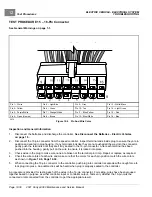
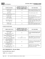
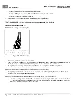
4.
Pin 6 Tan/Green Wire:
Lift bed, remove access cover, access the controller.
See following NOTE.
2021 Carryall 300 Maintenance and Service Manual
Page 12-19
Summary of Contents for Carryall 300 2021
Page 2: ......
Page 16: ......
Page 551: ...80 2018 by Kohler Co All rights reserved KohlerEngines com 17 690 15 Rev...
Page 565: ...GASOLINE ENGINE HARNESS Wiring Diagrams Gasoline Engine Harness 26...
Page 566: ...Page intentionally left blank...
Page 567: ...GASOLINE KEY START MAIN HARNESS Wiring Diagrams Gasoline Key Start Main Harness 26...
Page 568: ...Page intentionally left blank...
Page 569: ...GASOLINE PEDAL START MAIN HARNESS Wiring Diagrams Gasoline Pedal Start Main Harness 26...
Page 570: ...Page intentionally left blank...
Page 571: ...GASOLINE INSTRUMENT PANEL HARNESS Wiring Diagrams Gasoline Instrument Panel Harness 26...
Page 572: ...Page intentionally left blank...
Page 573: ...GASOLINE FNR HARNESS Wiring Diagrams Gasoline FNR Harness 26...
Page 574: ...Page intentionally left blank...
Page 575: ...ELECTRIC MAIN HARNESS Wiring Diagrams Electric Main Harness 26...
Page 576: ...Page intentionally left blank...
Page 577: ...ELECTRIC INSTRUMENT PANEL HARNESS Wiring Diagrams Electric Instrument Panel Harness 26...
Page 578: ...Page intentionally left blank...
Page 579: ...ELECTRIC ACCESSORIES HARNESS Wiring Diagrams Electric Accessories Harness 26...
Page 580: ...Page intentionally left blank...
Page 588: ...NOTES...
Page 589: ...NOTES...
Page 590: ...NOTES...
Page 591: ...NOTES...
Page 592: ...NOTES...
Page 593: ...NOTES...
Page 594: ...NOTES...
Page 595: ......
Page 596: ......


