


STEERING AND FRONT SUSPENSION
Front Wheel Bearings and Hubs
7
FRONT WHEEL BEARINGS AND HUBS
See General Warnings on page 1-1.
NOTE:
The front wheel bearings are pressed into the spindle and are not serviceable. If excessive free-play is
detected the entire hub should be replaced.
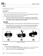
FRONT WHEEL FREE PLAY INSPECTION
1.
Raise the front of the vehicle.
2.
Use your hands to attempt to rock the wheel and hub assembly back and forth on the spindle. Movement of
the wheel and hub on the spindle indicates that the hub bearing is worn; therefore, the hub assembly must be
replaced.
See Front Hub Removal on page 7-21.
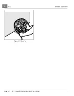
FRONT HUB REMOVAL
1.
Remove the front wheels.
See Wheel Removal on page 8-1.
2.
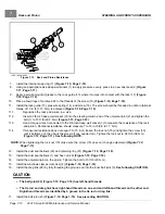
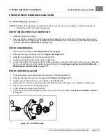
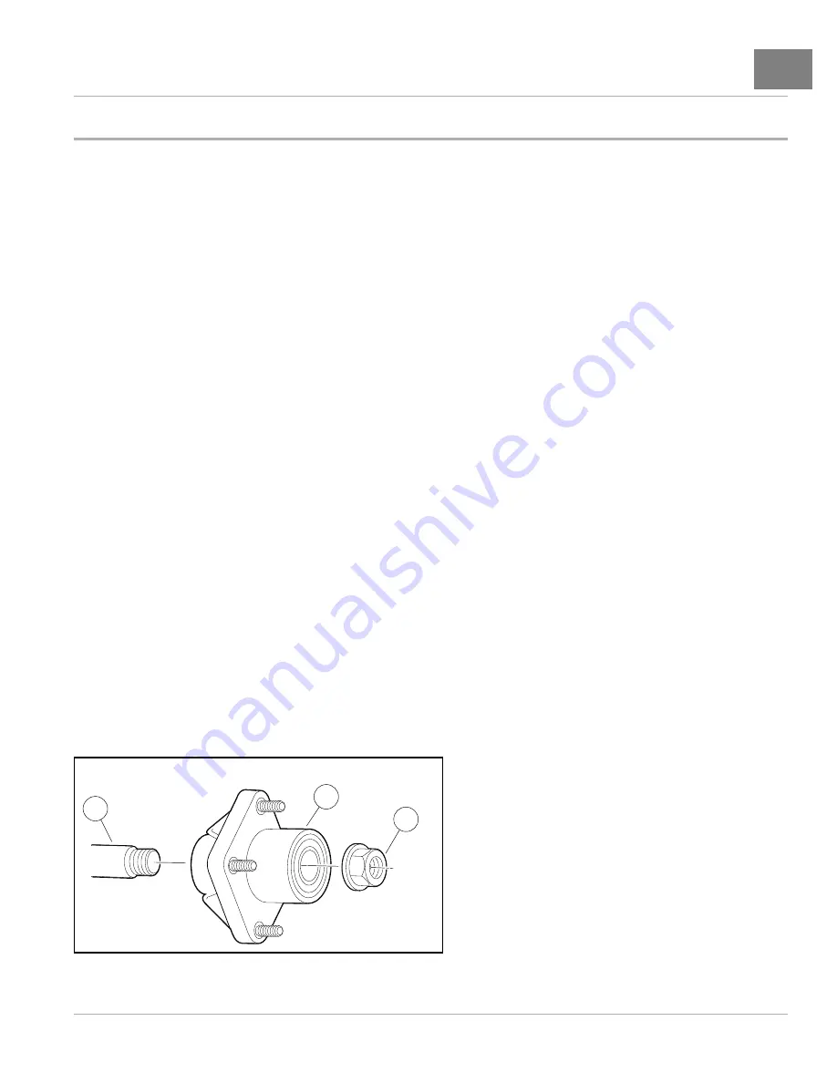
Remove dust cap (12) and lock nut (11)
.
3.
Slide the hub assembly (9) off of the spindle shaft (3).
4.
Lightly sand spindle shaft to clean away any light rust.
5.
Inspect the surface of the spindle shaft for surface damage. It should be clean and smooth. If severe pitting from
rust or corrosion has occurred, replace the spindle assembly.
See Kingpin and Steering Spindle Removal –
Maintenance-Free Ball Joints on page 7-17.
FRONT HUB INSTALLATION
1.
Clean and apply a light coat of anti-seize lubricant to the spindle shaft (3).
2.
Slide the hub assembly (9) onto the spindle shaft
.
3.
Install a new flanged lock nut (11) and tighten to 50 ft·lb (68 N·m).
4.
Rotate the hub. The hub should rotate smoothly without binding, side play, or any indication of rough spots.
5.
Repeat the procedure for the opposite wheel.
6.
Install wheels and finger-tighten lug nuts.
7.
Lower the vehicle and finish tightening lug nuts, using a crisscross pattern.
See Wheel Installation, Section
3
11
9
678
Figure 7-20
Front Wheel Hub
2021 Carryall 300 Maintenance and Service Manual
Page 7-21
Summary of Contents for Carryall 300 2021
Page 2: ......
Page 16: ......
Page 551: ...80 2018 by Kohler Co All rights reserved KohlerEngines com 17 690 15 Rev...
Page 565: ...GASOLINE ENGINE HARNESS Wiring Diagrams Gasoline Engine Harness 26...
Page 566: ...Page intentionally left blank...
Page 567: ...GASOLINE KEY START MAIN HARNESS Wiring Diagrams Gasoline Key Start Main Harness 26...
Page 568: ...Page intentionally left blank...
Page 569: ...GASOLINE PEDAL START MAIN HARNESS Wiring Diagrams Gasoline Pedal Start Main Harness 26...
Page 570: ...Page intentionally left blank...
Page 571: ...GASOLINE INSTRUMENT PANEL HARNESS Wiring Diagrams Gasoline Instrument Panel Harness 26...
Page 572: ...Page intentionally left blank...
Page 573: ...GASOLINE FNR HARNESS Wiring Diagrams Gasoline FNR Harness 26...
Page 574: ...Page intentionally left blank...
Page 575: ...ELECTRIC MAIN HARNESS Wiring Diagrams Electric Main Harness 26...
Page 576: ...Page intentionally left blank...
Page 577: ...ELECTRIC INSTRUMENT PANEL HARNESS Wiring Diagrams Electric Instrument Panel Harness 26...
Page 578: ...Page intentionally left blank...
Page 579: ...ELECTRIC ACCESSORIES HARNESS Wiring Diagrams Electric Accessories Harness 26...
Page 580: ...Page intentionally left blank...
Page 588: ...NOTES...
Page 589: ...NOTES...
Page 590: ...NOTES...
Page 591: ...NOTES...
Page 592: ...NOTES...
Page 593: ...NOTES...
Page 594: ...NOTES...
Page 595: ......
Page 596: ......


