


7
Steering Adjustment
STEERING AND FRONT SUSPENSION
STEERING ADJUSTMENT
See General Warnings on page 1-1.
1.
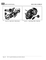
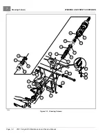
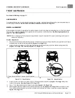
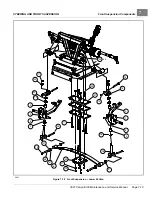
Turn the steering wheel all the way to the right. Note the distance between the passenger side spindle stop (2)
and passenger side A-plate (3)
. The internal stop on the rack must reach its limit of travel
against rack and pinion housing at exactly the same time the spindle stops against the passenger side A-plate
(with vehicle wheels turned to the right). If simultaneous contact occurs, steering is in correct adjustment; go to
step 4. If simultaneous contact does not occur, go to step 2.
2.
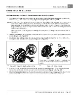
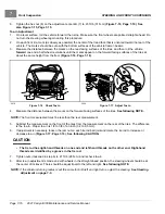
Loosen the nuts (27 and 29) and turn the drag link (28)
to adjust the drag link rod.
Adjust the link rod with the steering wheel turned all the way to the right, so the passenger side spindle stop
lightly touches the passenger side A-plate. The internal stop on the rack must reach its limit of travel at the
same time the spindle stops against the passenger side A-plate (with vehicle wheels turned to the right).
See
following CAUTION.
CAUTION
• The drag link has both left and right-hand threads. The end of the drag link toward the spindle has
left-hand threads, and the end toward the rack has right-hand threads. To prevent damage to threaded
parts, care should be taken when servicing the drag link.
3.
When all adjustments have been completed, tighten the nuts (27 and 29) on the drag link assembly with an open
end wrench. Tighten nuts to 21 ft·lb (28.4 N·m)
See following CAUTION.
CAUTION
• When tightening the nuts (27 and 29), make sure the drag link (28) does not turn (Figure 7-10, Page
4.
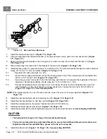
Straighten wheels and turn steering wheel from lock to lock. Wheels should turn smoothly and easily. If steering
wheel does not turn smoothly and easily, inspect steering assemblies as follows:
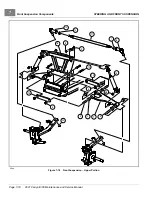
– ball joints (23)
and (6 and 13)
– spindle bushings (3 and 4)
– wave washers (20)
– rack assembly (17)
5.
Also inspect front suspension assemblies as follows:
– A-plates (1)
– urethane bushings (2)
– leaf springs (6)
6.
Replace components as necessary.
Page 7-6
2021 Carryall 300 Maintenance and Service Manual
Summary of Contents for Carryall 300 2021
Page 2: ......
Page 16: ......
Page 551: ...80 2018 by Kohler Co All rights reserved KohlerEngines com 17 690 15 Rev...
Page 565: ...GASOLINE ENGINE HARNESS Wiring Diagrams Gasoline Engine Harness 26...
Page 566: ...Page intentionally left blank...
Page 567: ...GASOLINE KEY START MAIN HARNESS Wiring Diagrams Gasoline Key Start Main Harness 26...
Page 568: ...Page intentionally left blank...
Page 569: ...GASOLINE PEDAL START MAIN HARNESS Wiring Diagrams Gasoline Pedal Start Main Harness 26...
Page 570: ...Page intentionally left blank...
Page 571: ...GASOLINE INSTRUMENT PANEL HARNESS Wiring Diagrams Gasoline Instrument Panel Harness 26...
Page 572: ...Page intentionally left blank...
Page 573: ...GASOLINE FNR HARNESS Wiring Diagrams Gasoline FNR Harness 26...
Page 574: ...Page intentionally left blank...
Page 575: ...ELECTRIC MAIN HARNESS Wiring Diagrams Electric Main Harness 26...
Page 576: ...Page intentionally left blank...
Page 577: ...ELECTRIC INSTRUMENT PANEL HARNESS Wiring Diagrams Electric Instrument Panel Harness 26...
Page 578: ...Page intentionally left blank...
Page 579: ...ELECTRIC ACCESSORIES HARNESS Wiring Diagrams Electric Accessories Harness 26...
Page 580: ...Page intentionally left blank...
Page 588: ...NOTES...
Page 589: ...NOTES...
Page 590: ...NOTES...
Page 591: ...NOTES...
Page 592: ...NOTES...
Page 593: ...NOTES...
Page 594: ...NOTES...
Page 595: ......
Page 596: ......


