


7
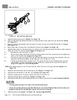
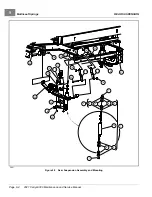
Front Suspension Components
STEERING AND FRONT SUSPENSION
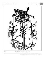
KINGPIN AND STEERING SPINDLE INSTALLATION – MAINTENANCE-FREE BALL JOINTS
1.
Inspect all parts and replace them as necessary.
2.
Install the kingpin (26) over the leaf spring eye. Insert the bolt (25) and install the nut (14)
. Tighten the bolt to 17 ft·lb (23 N·m).
3.
Install the wave washer (35).
4.
Install the steering spindle on the kingpin. Then install the thrust washer (19), flat washer (33), upper plate clevis
(16), conical washer (34), and nut (17). Tighten the nut to 65 ft·lb (88 N·m).
5.
Attach the tie rod ball joints (6 and 13) to the spindle tabs, then install and tighten the nuts (20) to 40 ft·lb (54
N·m)
6.
Install the drag link ball joint.
See Tie Rod and Drag Link Installation – Maintenance-Free Ball Joints on
7.
Install front hub and wheel.
See Front Hub Installation on page 7-21.
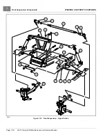
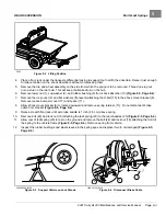
DELTA A-PLATE REMOVAL
1.
Remove front wheel(s).
See Wheel Removal, Section 8, Page 8-1.
2.
Remove bolts (10 and 24), A-Plate straps (14), and nuts (5)
.
3.
Remove the lower shock absorber mounting nut (38), then slide the shock absorber (15) free of the Delta
A-Plate (1).
4.
Remove the Delta A-Plate (1).
5.
Inspect the bushings (2) and sleeves (3 and 4) in the Delta A-Plate and replace them if necessary.
DELTA A-PLATE INSTALLATION
1.
Install the A-Plate (1) in reverse order of removal. Tighten the A-Plate suspension bolts (10 and 24) to 20
ft·lb (27 N·m)
2.
Tighten shock absorber mounting nut (38) to 20 ft·lb (27.1 N·m).
3.
Install the wheel(s).
See Wheel Installation, Section 8, Page 8-1.
4.
Adjust the wheel alignment.
See Wheel Alignment on page 7-15.
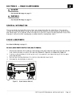
SHOCK ABSORBER REMOVAL
1.
Inspect the shock absorbers (15) for fluid leakage at the point where the shaft enters the shock absorber body.
Leaking shock absorbers should be replaced.
2.
Remove the nut (38) attaching the shock absorber to the A-Plate (1)
.
3.
Remove the nut (9) and bolt (8) attaching the shock absorber to the shock and gear support (18).
4.
Remove the shock absorber (15).
SHOCK ABSORBER INSTALLATION
NOTE:
When installing shock absorbers, make sure front shocks have identical part numbers and rear shocks
have identical part numbers.
1.
Install the shock absorber by reversing the removal procedure.
2.
Tighten the nuts (9 and 38) to 20 ft·lb (27 N·m).
Page 7-20
2021 Carryall 300 Maintenance and Service Manual
Summary of Contents for Carryall 300 2021
Page 2: ......
Page 16: ......
Page 551: ...80 2018 by Kohler Co All rights reserved KohlerEngines com 17 690 15 Rev...
Page 565: ...GASOLINE ENGINE HARNESS Wiring Diagrams Gasoline Engine Harness 26...
Page 566: ...Page intentionally left blank...
Page 567: ...GASOLINE KEY START MAIN HARNESS Wiring Diagrams Gasoline Key Start Main Harness 26...
Page 568: ...Page intentionally left blank...
Page 569: ...GASOLINE PEDAL START MAIN HARNESS Wiring Diagrams Gasoline Pedal Start Main Harness 26...
Page 570: ...Page intentionally left blank...
Page 571: ...GASOLINE INSTRUMENT PANEL HARNESS Wiring Diagrams Gasoline Instrument Panel Harness 26...
Page 572: ...Page intentionally left blank...
Page 573: ...GASOLINE FNR HARNESS Wiring Diagrams Gasoline FNR Harness 26...
Page 574: ...Page intentionally left blank...
Page 575: ...ELECTRIC MAIN HARNESS Wiring Diagrams Electric Main Harness 26...
Page 576: ...Page intentionally left blank...
Page 577: ...ELECTRIC INSTRUMENT PANEL HARNESS Wiring Diagrams Electric Instrument Panel Harness 26...
Page 578: ...Page intentionally left blank...
Page 579: ...ELECTRIC ACCESSORIES HARNESS Wiring Diagrams Electric Accessories Harness 26...
Page 580: ...Page intentionally left blank...
Page 588: ...NOTES...
Page 589: ...NOTES...
Page 590: ...NOTES...
Page 591: ...NOTES...
Page 592: ...NOTES...
Page 593: ...NOTES...
Page 594: ...NOTES...
Page 595: ......
Page 596: ......


