


STEERING AND FRONT SUSPENSION
Rack and Pinion
7
RACK AND PINION
See General Warnings on page 1-1.
CAUTION
• Front impacts that bend tie rods and/or drag links can possibly damage internal steering gear
components. See Rack and Pinion Inspection on page 7-7. The manufacturer recommends inspecting
the rack and pinion and replacing if damaged.
RACK AND PINION INSPECTION
1.
Look for obvious damage to the chassis, where the rack and pinion is mounted, and the rack and pinion housing.
Particularly check the housing for broken mounting points.
2.
Compare the toe-in against the specification.
See Toe-in Adjustment on page 7-16.
3.
If obvious visible damage is found, such as a bent tie rod, check the steering gear for abnormal free-play, noise,
binding or clunking while it is under a load. With the steering system fully assembled and all four tires on the
ground/floor, turn the steering wheel from stop to stop. While turning, feel for any binding, clunking or tight/loose
spots. Listen for unusual noises. Replace the rack and pinion as an assembly if any is found.
4.
In the event of an known impact and obvious visible damage is not found in the method described above,
disconnect the tie rods and/or drag links from the spindles. Turn the steering wheel from stop to stop. While
turning, feel for any binding or tight/loose spots. Listen for unusual noises. Replace the rack and pinion as an
assembly if any is found.
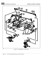
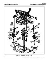
RACK AND PINION REMOVAL – MAINTENANCE-FREE BALL JOINTS
1.
Remove the front body.
See Front Body, Section 4, Page 4-3.
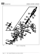
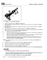
2.
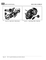
Remove the drag link ball joint retaining nut (25)
.
3.
Remove the outer drag link ball joint (23) from the spindle assembly (33) and inspect for excessive wear and
seal damage.
4.
Remove the bolts (30), washers (31), and lock nuts (32) from the steering rack assembly mounting bracket
5.
Remove the bolt (2) and flat washer (3) on the upper universal joint, then remove the rack assembly and universal
joint from the vehicle
2021 Carryall 300 Maintenance and Service Manual
Page 7-7
Summary of Contents for Carryall 300 2021
Page 2: ......
Page 16: ......
Page 551: ...80 2018 by Kohler Co All rights reserved KohlerEngines com 17 690 15 Rev...
Page 565: ...GASOLINE ENGINE HARNESS Wiring Diagrams Gasoline Engine Harness 26...
Page 566: ...Page intentionally left blank...
Page 567: ...GASOLINE KEY START MAIN HARNESS Wiring Diagrams Gasoline Key Start Main Harness 26...
Page 568: ...Page intentionally left blank...
Page 569: ...GASOLINE PEDAL START MAIN HARNESS Wiring Diagrams Gasoline Pedal Start Main Harness 26...
Page 570: ...Page intentionally left blank...
Page 571: ...GASOLINE INSTRUMENT PANEL HARNESS Wiring Diagrams Gasoline Instrument Panel Harness 26...
Page 572: ...Page intentionally left blank...
Page 573: ...GASOLINE FNR HARNESS Wiring Diagrams Gasoline FNR Harness 26...
Page 574: ...Page intentionally left blank...
Page 575: ...ELECTRIC MAIN HARNESS Wiring Diagrams Electric Main Harness 26...
Page 576: ...Page intentionally left blank...
Page 577: ...ELECTRIC INSTRUMENT PANEL HARNESS Wiring Diagrams Electric Instrument Panel Harness 26...
Page 578: ...Page intentionally left blank...
Page 579: ...ELECTRIC ACCESSORIES HARNESS Wiring Diagrams Electric Accessories Harness 26...
Page 580: ...Page intentionally left blank...
Page 588: ...NOTES...
Page 589: ...NOTES...
Page 590: ...NOTES...
Page 591: ...NOTES...
Page 592: ...NOTES...
Page 593: ...NOTES...
Page 594: ...NOTES...
Page 595: ......
Page 596: ......