12
Test Procedures
ELECTRIC VEHICLE - ELECTRICAL SYSTEM
TROUBLESHOOTING
TEST PROCEDURE 7 – Solenoid Activating Coil
See General Warnings on page 1-1.
NOTE:
This is a resistance test.
Be aware that one of two different solenoids may be found on the vehicle. Visually, the production solenoid is
smaller than the service replacement. On the labels, the larger service replacement solenoid has SOL0605
and the smaller production solenoid has SOL5006. Internally, specifications and test results differ between
the two.
1.
If necessary, see Testing Basics on page 12-12.
2.
Disconnect the batteries and discharge the controller.
See Disconnect the Batteries – Electric Vehicles
3.
Access the solenoid by removing the electronics module cover.
See Electric Vehicle - Electrical Components
4.
Remove the two small wire terminals from the solenoid.
5.
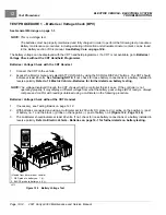
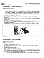
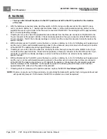
Place red (+) probe of the multimeter on the positive (+) solenoid terminal. Place the black (–) probe on the
other small solenoid terminal.
– A reading of 180 to 190 ohms should be obtained for service replacement solenoids
. If not, replace the solenoid.
+
2m
20
m
200
m
2k
200
200
200
200
20
2
200
m
500
20k
200k
2000
k
1000
OFF
WAVETEK
5XL
V
V
V
A
!
!
COM
200nA
MAX
1000 ---
750V
FUSED
1
2500-20000-10283
Figure 12-5
TEST PROCEDURE 8 – Pre-Charge Resistor
See General Warnings on page 1-1.
NOTE:
This is a resistance test.
1.
If necessary, see Testing Basics on page 12-12.
2.
Disconnect the batteries and discharge the controller.
See Disconnect the Batteries – Electric Vehicles
3.
Access the solenoid by lifting the bed.
4.
Remove wires between 2 large posts of solenoid.
5.
Measure resistance between the two large posts of the solenoid. The reading should be approximately 250 ohms.
If not, remove pre-charge resistor, with pre-charge resistor removed, if it does not read approximately 250 ohms
and is not discolored, replace.
.
5.1.
If it reads less than 250 ohms and is discolored replace and check pre-charge resistor. Go to Motor Test
Procedure 1.
Page 12-22
2021 Carryall 300 Maintenance and Service Manual
Summary of Contents for Carryall 300 2021
Page 2: ......
Page 16: ......
Page 551: ...80 2018 by Kohler Co All rights reserved KohlerEngines com 17 690 15 Rev...
Page 565: ...GASOLINE ENGINE HARNESS Wiring Diagrams Gasoline Engine Harness 26...
Page 566: ...Page intentionally left blank...
Page 567: ...GASOLINE KEY START MAIN HARNESS Wiring Diagrams Gasoline Key Start Main Harness 26...
Page 568: ...Page intentionally left blank...
Page 569: ...GASOLINE PEDAL START MAIN HARNESS Wiring Diagrams Gasoline Pedal Start Main Harness 26...
Page 570: ...Page intentionally left blank...
Page 571: ...GASOLINE INSTRUMENT PANEL HARNESS Wiring Diagrams Gasoline Instrument Panel Harness 26...
Page 572: ...Page intentionally left blank...
Page 573: ...GASOLINE FNR HARNESS Wiring Diagrams Gasoline FNR Harness 26...
Page 574: ...Page intentionally left blank...
Page 575: ...ELECTRIC MAIN HARNESS Wiring Diagrams Electric Main Harness 26...
Page 576: ...Page intentionally left blank...
Page 577: ...ELECTRIC INSTRUMENT PANEL HARNESS Wiring Diagrams Electric Instrument Panel Harness 26...
Page 578: ...Page intentionally left blank...
Page 579: ...ELECTRIC ACCESSORIES HARNESS Wiring Diagrams Electric Accessories Harness 26...
Page 580: ...Page intentionally left blank...
Page 588: ...NOTES...
Page 589: ...NOTES...
Page 590: ...NOTES...
Page 591: ...NOTES...
Page 592: ...NOTES...
Page 593: ...NOTES...
Page 594: ...NOTES...
Page 595: ......
Page 596: ......


