


REAR SUSPENSION
Jounce Bumpers
9
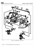
MULTI-LEAF SPRING INSTALLATION
NOTE:
When installing rear leaf springs, make sure that both springs have identical part numbers.
Tighten flange bolt (19) after clamp from brake cable has been positioned between nut and frame component.
1.
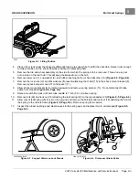
Place front of leaf spring (20) into vehicle frame and insert bolt (22) through frame and leaf spring eye
. Install lock nut (18) and tighten to 17 to 20 ft·lb (24 to 28 N·m).
2.
Align the other end of leaf spring with the holes in the spring shackles (23). Insert bolt (22) through leaf spring
eye and shackles. Install lock nut (18) and tighten to 17 to 20 ft·lb (24 to 28 N·m). Lower transaxle onto leaf
spring (20).
See following CAUTION
.
CAUTION
• When placing transaxle on spring, be sure to position locating bolt on the spring in the locating
hole in the transaxle saddle.
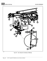
3.
Tighten the nuts (1) until the rubber bushing (8) expands to the size of the cup washer (9).
4.
Install spring retainer (13) and shock mount bracket (6) onto locating bolt at bottom center of leafspring
.
See preceding CAUTION.
5.
Position jounce bumper mount (17) with spacer (11) onto axle tube. Install U-bolt (15), flat washers (if present),
and lock nuts (12). Tighten U-bolt to 22 to 27 ft·lb (30 to 37 N·m).
.
6.
Install shock absorber.
See Shock Absorber Installation on page 9-2.
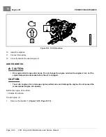
JOUNCE BUMPERS
See General Warnings on page 1-1.
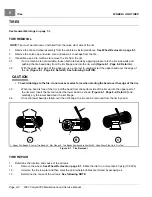
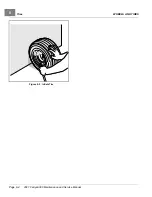
JOUNCE BUMPER REMOVAL
1.
Grip jounce bumper (18) and pull from bumper mount (12).
JOUNCE BUMPER INSTALLATION
1.
Insert jounce bumper (18) into bumper mount (12).
Make sure the entire circumference of bumper is seated firmly in mounting hole.
2021 Carryall 300 Maintenance and Service Manual
Page 9-5
Summary of Contents for Carryall 300 2021
Page 2: ......
Page 16: ......
Page 551: ...80 2018 by Kohler Co All rights reserved KohlerEngines com 17 690 15 Rev...
Page 565: ...GASOLINE ENGINE HARNESS Wiring Diagrams Gasoline Engine Harness 26...
Page 566: ...Page intentionally left blank...
Page 567: ...GASOLINE KEY START MAIN HARNESS Wiring Diagrams Gasoline Key Start Main Harness 26...
Page 568: ...Page intentionally left blank...
Page 569: ...GASOLINE PEDAL START MAIN HARNESS Wiring Diagrams Gasoline Pedal Start Main Harness 26...
Page 570: ...Page intentionally left blank...
Page 571: ...GASOLINE INSTRUMENT PANEL HARNESS Wiring Diagrams Gasoline Instrument Panel Harness 26...
Page 572: ...Page intentionally left blank...
Page 573: ...GASOLINE FNR HARNESS Wiring Diagrams Gasoline FNR Harness 26...
Page 574: ...Page intentionally left blank...
Page 575: ...ELECTRIC MAIN HARNESS Wiring Diagrams Electric Main Harness 26...
Page 576: ...Page intentionally left blank...
Page 577: ...ELECTRIC INSTRUMENT PANEL HARNESS Wiring Diagrams Electric Instrument Panel Harness 26...
Page 578: ...Page intentionally left blank...
Page 579: ...ELECTRIC ACCESSORIES HARNESS Wiring Diagrams Electric Accessories Harness 26...
Page 580: ...Page intentionally left blank...
Page 588: ...NOTES...
Page 589: ...NOTES...
Page 590: ...NOTES...
Page 591: ...NOTES...
Page 592: ...NOTES...
Page 593: ...NOTES...
Page 594: ...NOTES...
Page 595: ......
Page 596: ......


