


Description of the Software Modules and Parameters
Parameter manual
b maXX
BM5800
Document No.: 5.16029.03
73
3
Valid values:
Generally:
m
The band width of the current controller is inversely proportional to the current control-
ler cycle time.
m
The noise of the motor caused by the voltage signals in pulse form, drops with an in-
creasing PWM frequency.
m
The thermal loading in the IGBT model decreases along with falling PWM frequency.
Therefore the attainable peak current length increases with falling PWM frequency at
constant peak current while the nominal current of the device increases during contin-
uous operation.
m
The adjusting range of the output frequency increases if the current controller cycle
time sinks. This adjusting range refers to the stationary operation and to the linear
range of the PWM - that means without an overmodulation and provides frequencies
that generate excellent output voltages.
n
The quality of the generated output voltages is given by how close they are to the
effects of ideal sine voltages and depends on the ratio current controller frequency
f
I-R
(f
I-R
= 1/current controller cycle time) to the maximum output frequency f
max
:
f
max
= f
I-R
/ K
pf
. The greater the proportional factor K
pf
the better the quality is which
is reached. A multiple of 6 is preferred for K
pf
because of the 60° symmetry of the
three-phase system or of the voltage in the voltage space vector. Typically the
K
pf
= 18 is selected to provide a good quality.
n
The adjusting range is determined as follows (see chapter "Electrical data" in the in-
struction handbook of the device.
*) 900 Hz are technically (from the control point of view) possible
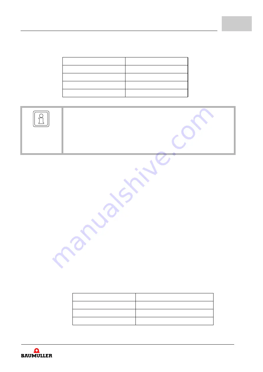
PWM Frequency
Current controller cycle time
2 kHz
250 µs
4 kHz
125 µs
8 kHz
62,5 µs
16 kHz
62,5 µs
NOTE!
If it is intended to operate a PWM frequency of 2 kHz at an
axis unit
, it first must be
checked if the operation of the drive is permitted (e.g. if the rated values of the motor,
or of the motor filter if one is at use still are valid for this PWM frequency). At a switch-
ing frequency of 2 kHz the current controller cycle time is 250 µs - so the adjusting
range of the output frequency is 0 to 225 Hz (see the electrical data in the instruction
handbook of the device).
Current controller cycle time Output frequency adjusting range
250 µs
0 - 225 Hz
125 µs
0 - 450 Hz
62,5 µs
0 - 599 Hz (900 Hz) *)


