4-24 Protection
and
Control BE1-CDS220
Table 4-11 summarizes the operating settings for Instantaneous Overcurrent.
Table 4-11. Operating Settings for Instantaneous Overcurrent
Range
Setting
5 A
1 A
Increment
Unit of
Measure
Default
Pickup
0 = Disabled
0.5 to 150
0 = Disabled
0.1 to 30
0.01 for 0.01 to 9.99
0.1 for 10.0 to 99.9
1.0 for 100 to 150
Secondary
amps
0
0 to 999 milliseconds
1 m
Milliseconds
0.1 to 60 seconds
0.1 for 0.1 to 9.9 sec
1.0 for 10 to 60 sec
Seconds
Time Delay
0 to 3600 (60 Hz) or 0 to 2500 (50 Hz)
∗
Cycles
0
∗
Time delays less than 10 cycles can be entered to the nearest 0.1 cycles from the optional HMI. All time
delays can be entered to the nearest 0.01 cycles from the ASCII command interface. Time delays entered
in cycles are converted to milliseconds or seconds. Increment precision after conversion is limited to that
appropriate for each of those units of measure.
Retrieving Instantaneous Overcurrent Status from the Relay
The status of each logic variable can be determined from the ASCII command interface using the RG-
STAT command. See Section 6, Reporting and Alarm Functions, General Status Reporting, for more
information.
51 - Time Overcurrent Protection
There are three independent functions for phase (51P, 151P, 251P), three for neutral (51N, 151N, 251N),
and three for negative-sequence (51Q, 151Q, 251Q) inverse time overcurrent protection. Each function
can be attached to either of the two hardware CT input circuits by the BESTlogic mode setting.
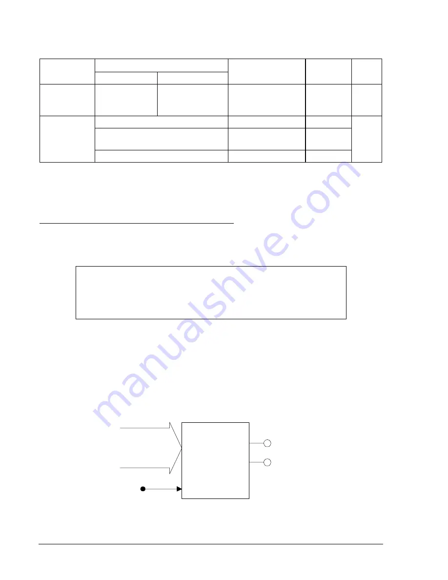
Figure 4-21 shows the 51P (phase time overcurrent) as a typical 51 function. Each of the nine
independent functions has two logic outputs #51nPU (picked up) and #51nT (trip) where n indicates
whether it is a P (phase), N (neutral), or Q (negative-sequence). The # differentiates between the
protective functions (51, 151, or 251).
D2843-03
07-24-00
BLK
51PT
Mode =
0-disable
1-ct ckt 1
2-ct ckt 2
SL-51P
LOGIC
51PPU
Figure 4-21. Time Overcurrent Logic Block
NOTE
When changing settings with the relay in service, an error message (PU TOO
LOW) will be generated if the new setting is within approximately 90% of the
metered current level. This is intended to prevent the user from inadvertently
causing a trip when changing a setting.
Summary of Contents for BE1-CDS220
Page 2: ......
Page 10: ...viii Introduction BE1 CDS220 This page intentionally left blank...
Page 36: ...ii Quick Start BE1 CDS220 This page intentionally left blank...
Page 48: ...ii Input And Output Functions BE1 CDS220 This page intentionally left blank...
Page 66: ...iv Protection and Control BE1 CDS220 This page intentionally left blank...
Page 112: ...ii Metering BE1 CDS220 This page intentionally left blank...
Page 116: ...5 4 Metering BE1 CDS220 This page intentionally left blank...
Page 166: ...ii BESTlogic Programmable Logic BE1 CDS220 This page intentionally left blank...
Page 176: ...7 10 BESTlogic Programmable Logic BE1 CDS220 This page intentionally left blank...
Page 234: ...8 56 Application BE1 CDS220 This page intentionally left blank...
Page 236: ...ii Security BE1 CDS220 This page intentionally left blank...
Page 240: ...9 4 Security BE1 CDS220 This page intentionally left blank...
Page 242: ...ii Human Machine Interface BE1 CDS220 This page intentionally left blank...
Page 256: ...10 14 Human Machine Interface BE1 CDS220 This page intentionally left blank...
Page 258: ...ii ASCII Command Interface BE1 CDS220 This page intentionally left blank...
Page 422: ...14 32 BESTCOMS Software BE1 CDS220 This page intentionally left blank...
Page 424: ...ii Time Current Characteristics BE1 CDS220 This page intentionally left blank...
Page 452: ...ii Terminal Communication BE1 CDS220 This page intentionally left blank...
Page 456: ...C 4 Terminal Communication BE1 CDS220 This page intentionally left blank...
Page 458: ...ii Settings Calculations BE1 CDS220 This page intentionally left blank...
Page 475: ......


