8-30 Application BE1-CDS220
51N
ModeG
51NT
51NPU
151P
Mode1
151PT
151PPU
151N
Mode1
151NT
151NPU
151Q
Mode1
151QT
151QPU
OPTO
OPTO
IN2 Breaker2 Status
OPTO
OPTO
D2850-02.vsd
09-28-99
ACTIVE
SETTING
GROUP
CONTROL
Mode2
SG0
SG2
SG1
SG3
BLK
BLK
BLK
BLK
AUTO
D3
D2
D1
D0
12
Note: For clarity, multiple variables
going to the same OR Gate are shown
by a single line into the OR Gate.
50TP
Mode2
50TPT
50TPPU
50TN
Mode2
50TNT
50TNPU
50TQ
Mode2
50TQT
50TQPU
BLK
BLK
BLK
12
VO11
PROT
TRIP
VO12
PROT PU
VOA
Relay
Trouble
OUTA
Output
Logic
VO1
86T Trip
OUT1
Output
Logic
VO2
86B Trip
OUT2
Output
Logic
VO3
52-2
86F Trip
OUT3
Output
Logic
4
VO4
52-2 Trip
OUT4
Output
Logic
VO5
52-2
Close
OUT5
Output
Logic
Feeder
Backup
Mode
Output
Logic
OPTO
OPTO
OPTO
OPTO
VO15
Test Mode
Alarm Point 23
OUT6
251P
Mode2
251PT
251PPU
251N
Mode2
251NT
251NPU
251Q
Mode2
251QT
251QPU
BLK
BLK
BLK
7
7
6
101
Mode1
101T
52-2
Trip
8
2
3
101C
52-2
Close
101SC
VO10
BFI-BF
4
BF
Mode2
INI
BLK
BFT
BFPU
62
Mode1
INI
62
BLK
VO9
BFI-62
3
250TP
Mode2
250TPT
250TPPU
250TN
Mode2
250TNT
250TNPU
250TQ
Mode2
250TQT
250TQPU
BLK
BLK
BLK
5
2
2
87
Mode1
87RT
87RPU
BLK
87UT
2NDHAR
5THHAR
43
Mode2
DIFF Cutoff
43
VO13
DIFF Cutoff
Alarm Point 21
IN1 Breaker1 Status
IN3 86T Status
IN4 86B Status
IN5 Feeders OK
IN6 BFI w/52B SUPV
IN7 BFI w/50 SUPV
IN8 Test
Mode Disable
743
Mode2
Test Mode
Enable
243
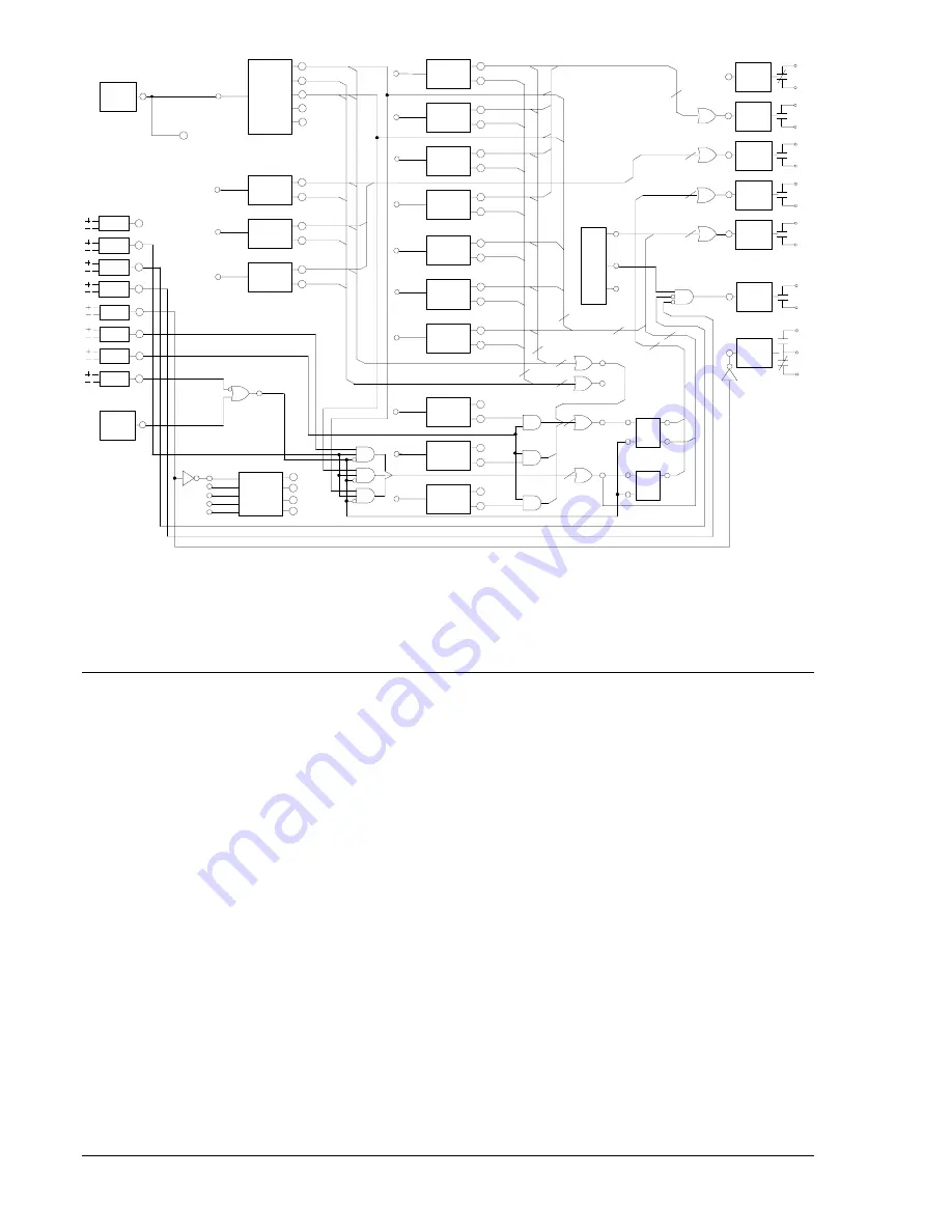
Figure 8-9. Typical Logic Diagram for TX-W-BU
BUS WITH BACKUP SCHEME
The BUS With Backup (BUS-W-BU) scheme was designed to provide low impedance, high-speed phase
and ground bus fault protection for distribution buses. This scheme also includes a high-speed bus-
interlocking scheme that provides a second level of bus protection and Feeder Relay out of Service
backup protection. Figure 8-10 shows the interconnection of BE1-851 or BE1-951 relays for backup and
feeder protection and the BE1-CDS220 (BUS-W-BU). Figure 8-11 shows the interconnection of a BE1-
CDS220 (TX-W-BU) for backup protection, a BE1-851 or BE1-951 for feeder protection, and the BE1-
CDS220 for bus protection. When interconnected with feeder relays using preprogrammed feeder logic
(FDR-W-IL), the BUS-W-BU scheme provides complete backup, except for reclosing, for the feeder relays
if relay failure occurs or when they are out of service for testing or maintenance. Virtual control switch logic
is used for local or remote (SCADA) control and can be used to replace the equivalent panel control
switches.
The control switch elements are referred to as virtual because they have no physical form, they exist only
in logic form, and they can only be operated via the ASCII command interface or the front panel. The
virtual 101 switch is used to trip and close the bus main breaker, virtual control switch 43 is used to turn off
the 87 protection element, and 743 is used to select test mode enable. The user may choose to eliminate
the use of external switches, as the virtual switches are fully functional equivalents of their physical
counterparts.
Figure 8-12 is a one-line drawing and Figure 8-13 is a logic drawing that represent the logic settings
shown in Table 8-21. In Table 8-21, the user can see the protection and control elements that are enabled
for the BUS-W-BU application and how the elements are logically wired together (equations). If the user
should decide to build on this scheme, all elements required for a more detailed application are available
through programming. For programming details, refer to Section 7, BESTlogic Programmable Logic.
Summary of Contents for BE1-CDS220
Page 2: ......
Page 10: ...viii Introduction BE1 CDS220 This page intentionally left blank...
Page 36: ...ii Quick Start BE1 CDS220 This page intentionally left blank...
Page 48: ...ii Input And Output Functions BE1 CDS220 This page intentionally left blank...
Page 66: ...iv Protection and Control BE1 CDS220 This page intentionally left blank...
Page 112: ...ii Metering BE1 CDS220 This page intentionally left blank...
Page 116: ...5 4 Metering BE1 CDS220 This page intentionally left blank...
Page 166: ...ii BESTlogic Programmable Logic BE1 CDS220 This page intentionally left blank...
Page 176: ...7 10 BESTlogic Programmable Logic BE1 CDS220 This page intentionally left blank...
Page 234: ...8 56 Application BE1 CDS220 This page intentionally left blank...
Page 236: ...ii Security BE1 CDS220 This page intentionally left blank...
Page 240: ...9 4 Security BE1 CDS220 This page intentionally left blank...
Page 242: ...ii Human Machine Interface BE1 CDS220 This page intentionally left blank...
Page 256: ...10 14 Human Machine Interface BE1 CDS220 This page intentionally left blank...
Page 258: ...ii ASCII Command Interface BE1 CDS220 This page intentionally left blank...
Page 422: ...14 32 BESTCOMS Software BE1 CDS220 This page intentionally left blank...
Page 424: ...ii Time Current Characteristics BE1 CDS220 This page intentionally left blank...
Page 452: ...ii Terminal Communication BE1 CDS220 This page intentionally left blank...
Page 456: ...C 4 Terminal Communication BE1 CDS220 This page intentionally left blank...
Page 458: ...ii Settings Calculations BE1 CDS220 This page intentionally left blank...
Page 475: ......


