2.15.3
Network Tab
fig.100:
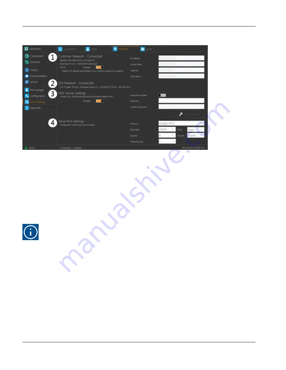
Network tab display
This tab is used to display the status of the panel’s network connections. It also allows the user to modify certain
settings. These options may only be modified by a user with service level or higher permissions.
1.
Customer Network
This section displays the current network connection, if applicable. The switch displayed in this section is
used to select whether
DHCP
, Dynamic Host Configuration Protocol, is enabled. If
DHCP
is enabled, the
panel will automatically search for a network connection and will fill in the
IP Address, Subnet Mask, Gate-
way
and
DNS Server
fields without user input. If
DCHP
is disabled, the values in these fields must be
entered manually. If the panel successfully connects to the chosen network, the title of this section will dis-
play
Customer Network – Connected
. Otherwise, it will display
Customer Network – Disconnected
.
Hint!
The IP Address Range 192.168.254.0 through 192.168.254.255 is reserved for the I/O Ethernet
network Setup. To ensure the functionality of both networks, do not use this range for the cus-
tomer LAN Connection.
2.
I/O Network
This section is used to display the
IP Address
and
MAC Address
of the panel’s I/O network coupler, if appli-
cable. These values may not be modified and are only visible for users with access level of Service or
higher. If the panel successfully connects to an appropriate network location, the title of this section will dis-
play
I/O Network – Connected
. Otherwise, it will display
I/O Network – Disconnected
.
3.
VNC Server Settings
This section is used to select whether a user may remotely log into the panel using
VNC
and whether a
password is required to do so. This section contains two switches. The switch on the left toggles whether
VNC client access is enabled for the panel and the switch on the right toggles whether a password is
required. If a password is required, it may be changed by typing a new password into the
Password
and
Confirm Password
fields and touching the
Change Password
button below.
User interface
Panel Settings
Instruction Manual | GEA Omni™
Control panel
100
GEA Refrigeration North America, Inc. | E_806550_2 | Generated 12.01.2016
Содержание Omni
Страница 1: ...Control panel GEA Omni Instruction Manual E_806550_2 ...
Страница 238: ......


