background image

LSM 510 

OPERATION IN EXPERT MODE 


LSM 510 META 

Display and Analysis of Images 

Carl Zeiss 


03/06 

B 45-0021 e 

4-335 


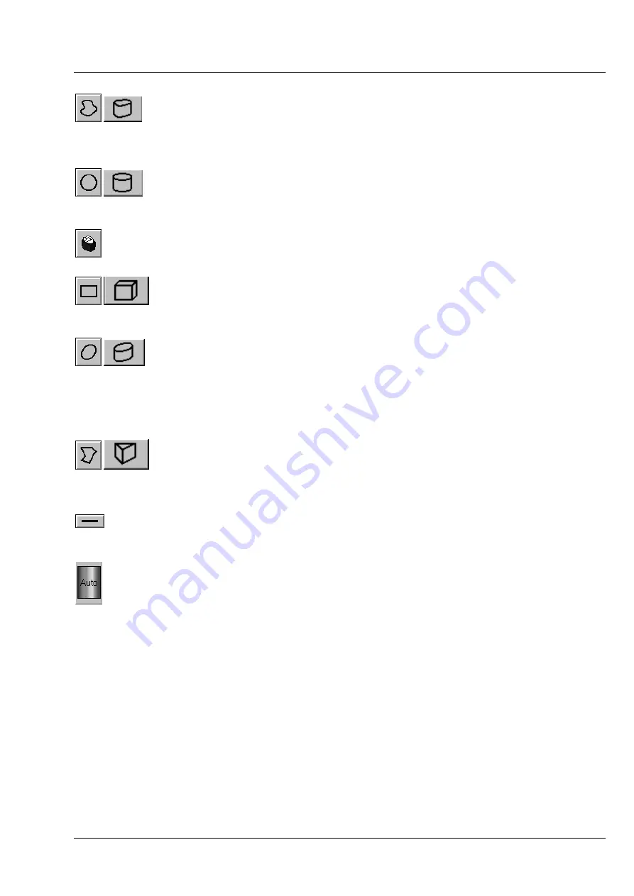
Bezier 

and

 3D Bezier 

button: Activates the Bezier figure drawing 

mode. The first click sets the starting point, each additional click adds a 
further line, a double-click on the starting point closes the figure and 
ends the procedure. 


Circle and 3D Circle 

button: Activates the circle drawing mode. 

Clicking and holding down the mouse button sets the center point; 
drag the diameter and release the mouse button to end the procedure.


Recycle bin

 button: All the ROIs to the image are deleted.   


Rectangle and 3D Rectangle 

button: Activates the rectangle drawing 

mode. Click and hold down the mouse button, drag the rectangle in 
any direction, release the mouse button to end the procedure. 


Ellipse 

and

 3D Elipse 

button: Activates the ellipse drawing mode. The 

first click sets the center point, the displayed line permits the 
determination of the first dimension, the second click sets the first 
dimension, the second dimension and the rotation direction can then be 
determined; the third click sets the second dimension and the direction 
and ends the procedure. 


Polyline 

and

 3D Polyline 

button: Activates polyline drawing mode. The 

first click sets the starting point, each additional click adds a further line, 
a double-click on the starting point closes the figure and ends the 
procedure.  


Line

 button: This button allows you to determine the line thickness of 

the ROI outline. 


Color / Auto

 button: One color from the list of colors can be assigned 

to all ROIs. When 

Auto

 is pressed, the outlines of all ROIs are 

automatically colored differently. 


Summary of Contents for LSM 510

Page 1: ...LSM 510 LSM 510 DuoScan LSM 510 META LSM 510 META DuoScan Release 4 0 March 2006...

Page 2: ...ce Unless expressly authorized forwarding and duplication of this document and the utilization and communication of its contents are not permitted Violations will entail an obligation to pay compensat...

Page 3: ...ally solve your work problem It represents a practical tip which will help you to find out which settings and methods are capable of improving or accelerating a procedure The HOT SURFACE symbol warns...

Page 4: ...f the LSM menu structure The step by step description how to get an image will be shown by typical application examples including the WINDOWS XP graphic user environment 5 VBA Programming for LSM 6 Ro...

Page 5: ...4 Notes on Setting up the Microscope System 1 12 1 5 Power Requirements 1 14 1 6 Notes on Handling the Laser Components 1 15 1 7 Physical Dimensions 1 17 1 8 Environmental Requirements 1 17 1 9 Notes...

Page 6: ...ate any claim under warranty including parts not directly affected by such action This also includes the modification of the system computer with new cards etc by the user The use of a camera at the b...

Page 7: ...ive a free replacement Description of labels Caution Faults and hazards that might arise during operation which might cause damage to the unit or injury to the user Attention Laser irradiation hazards...

Page 8: ...Scan Carl Zeiss Warning and Information Labels LSM 510 META DuoScan 1 4 B 45 0021 e 03 06 1 1 ZERO FOCUS OBJECTIVE REFLECTOR Fig 1 1 Warning and information labels on the Axiovert 200 M microscope wit...

Page 9: ...NOTES ON DEVICE SAFETY LSM 510 META Warning and Information Labels Carl Zeiss 03 06 B 45 0021 e 1 5 Fig 1 2 Warning and information labels on the Axio Imager Z1 microscope with LSM 510 META scanning...

Page 10: ...Carl Zeiss Warning and Information Labels LSM 510 META DuoScan 1 6 B 45 0021 e 03 06 1 0 2 0 3 0 4 0 5 0 6 0 7 0 8 0 90 10 0 Fig 1 3 Warning and information labels on the Axioskop 2 FS MOT microscope...

Page 11: ...A Warning and Information Labels Carl Zeiss 03 06 B 45 0021 e 1 7 Fig 1 4 Warning and information labels on LSM DuoScan systems LSM 510 DuoScan or LSM 510 META DuoScan only Fig 1 5 Warning and informa...

Page 12: ...NOTES ON DEVICE SAFETY LSM 510 DuoScan Carl Zeiss Warning and Information Labels LSM 510 META DuoScan 1 8 B 45 0021 e 03 06 Fig 1 6 Warning and information labels on laser components page 1...

Page 13: ...LSM 510 NOTES ON DEVICE SAFETY LSM 510 META Warning and Information Labels Carl Zeiss 03 06 B 45 0021 e 1 9 Fig 1 7 Warning and information labels on laser module LSM 5 LIVE...

Page 14: ...ng and Information Labels LSM 510 META DuoScan 1 10 B 45 0021 e 03 06 EnTERPRISE COHEREnT COHEREnT EnTERPRISE E4 J3 7 SE AR CH PE AK J6 E4 E5 wa ter OU T ma xim um wa ter pre ssure 60 p s I Fig 1 8 Wa...

Page 15: ...y and laboratory use EMC requirements Low voltage directive 73 23 EWG EMC directive 89 336 EWG The company works according to a certified Environment Management System according to ISO 14001 The Produ...

Page 16: ...sion leads The system contains components with dangerous voltage The system must not be opened by anybody else than authorized Carl Zeiss Service staff Before opening the main plug has to be disconnec...

Page 17: ...inst laser radiation are provided Tube openings or other unused mounts should always be protected against dust and moisture with the corresponding device components or with termination covers blind pl...

Page 18: ...outlet must be equipped with a fuse having minimum tripping characteristic C according to IEC EN 60898 Line voltage 220 240 V AC 10 100 125 V AC 10 Line frequency 50 60 Hz 50 60 Hz LSM incl VIS laser...

Page 19: ...SS 561 nm 3B 10 mW 6 HeNe 594 nm 3B 2 mW 7 HeNe 633 nm 3B 5 mW 8 Titanium Sapphire Laser Mai Tai Spectra Physics 710 990 nm depending on the model 4 2 W 9 Titanium Sapphire Laser Chameleon Coherent 71...

Page 20: ...class 4 lasers take special care of fire protection requirements Do not use or store flammable or explosive solids fluids or gases in the vicinity of the system Class 4 lasers can inflame also flamma...

Page 21: ...66 52 22 30 Plug in unit external laser 66 52 22 9 System Electronic Rack 110 70 58 90 Power supply for Ar UV 50 50 30 30 Cooling unit for Ar UV 80 45 50 30 Laser Module LIVE 66 52 22 58 1 8 Environm...

Page 22: ...a on a diskette is stored in the form of magnetic signals To some extent monitors telephones or even lamps generate magnetic fields that might destroy this data Also never open the metal cover on disk...

Page 23: ...During maintenance or repair carried out by the service personnel the customer is requested to stand aside and wear a pair of laser safety goggles if needed Before opening the housing of the halogen l...

Page 24: ...ing Mirror The ports of the lamps the switching mirror and the transmission PMT are equipped with hardware interlock devices At most ports all ports of the Axioskop 2 FS MOT and the Axio Imager Z1 as...

Page 25: ...Do not remove the sensor ring from the microscope This might result in failure of laser safety and a non operating system For mounting any lamp TPMT or the switching mirror back onto the microscope r...

Page 26: ...LSM 510 META scan head Remove the blue cover from the back of the scan head Fig 1 13 and Fig 1 14 Fig 1 13 Rear view of META scan head Fig 1 14 Rear view of META scan head with blue cover removed Loos...

Page 27: ...2 FS MOT and Axio Imager Z1 Slowly pull the scan head away from the microscope port or the tube For mounting the scan head onto a microscope make sure the pins and the electronic connections of the sa...

Page 28: ...r tube counter clockwise to unscrew the tube Fig 1 21 4 from the small black tube which is fixed to the scan head Now the tube can be removed and you can proceed as described above For rearranging the...

Page 29: ...ert 200 M or Axio Imager Z1 Fig 1 23 1 and Fig 1 24 1 This connection has to be unplugged from the microscope which is not in use and plugged into the microscope to be used following the exchange of t...

Page 30: ...Remove the connection of the microscope no longer in use at the electronics rack and plug in the connection of the microscope which should be used instead 3 After the connections of the non used micr...

Page 31: ...erted 2 2 m x 4 2 m 2 4 2 1 4 LSM with Ar UV Laser 2 5 2 1 5 LSM 510 or LSM 510 META equipped with LSM DuoScan UV 2 7 2 1 6 LSM prepared for Two Photon Laser NLO 2 8 2 2 Power Requirements 2 10 2 3 Ph...

Page 32: ...2 m 3 50 m Fig 2 1 Space requirements for LSM on large system table measurements in mm The System Electronic Rack contains all electronics for control of the hardware components of the LSM system the...

Page 33: ...LSM on small system table measurements in mm The System Electronic Rack contains all electronics for control of the hardware components of the LSM system the power supply for the microscope the scanni...

Page 34: ...ed by 90 measurements in mm The System Electronic Rack contains all electronics for control of the hardware components of the LSM system the power supply for the microscope the scanning unit the Laser...

Page 35: ...0021 e 2 5 2 1 4 LSM with Ar UV Laser We recommend placing the cooling unit of the Ar laser UV in a separate room to prevent heat accumulation and vibration Length of the water hose 400 cm One microsc...

Page 36: ...e System Electronic Rack contains all electronics for control of the hardware components of the system the power supply for the microscope the scanning unit and the Laser Module RGB equipped with the...

Page 37: ...UV Laser measurements in mm The System Electronic Rack contains all electronics for control of the hardware components of the LSM system the power supply for the microscope the scanning unit and the L...

Page 38: ...dware components of the system the power supply for the microscope the scanning unit and the Laser Module RGB equipped with the choice of lasers The Laser Module RGB is set on top of the System Electr...

Page 39: ...he microscope the scanning unit and the Laser Module RGB equipped with the choice of lasers The Laser Module RGB is set on top of the System Electronic Rack Power supply and cooling unit of the NLO La...

Page 40: ...ins socket outlet must be equipped with a fuse having minimum tripping characteristic C according to IEC EN 60898 Line voltage 220 240 V AC 10 100 125 V AC 10 Line frequency 50 60 Hz 50 60 Hz LSM incl...

Page 41: ...Requirements Carl Zeiss 03 06 B 45 0021 e 2 11 Fig 2 9 Power connector for LSM 510 LSM 510 META and Laser Module V Free reserve outlets may be used to supply power to additional equipment No more than...

Page 42: ...AND LSM 510 META SETUP REQUIREMENTS LSM 510 DuoScan Carl Zeiss Power Requirements LSM 510 META DuoScan 2 12 B 45 0021 e 03 06 Fig 2 10 Power connector for Laser Module RGB Scheme is turned 90 to real...

Page 43: ...lock interface Fig 2 11 Key interlock Laser ON OFF and interface for connection of door interlock The door interlock interface is covered with a green plug to bypass a door interlock To use the interf...

Page 44: ...ble NLO for Verdi Mira or Millenia Tsunami Laser 180 140 75 400 Scanning Module LSM 510 25 20 25 15 Scanning Module LSM 510 META 28 27 30 5 13 Scanning Module LSM DuoScan 40 15 13 8 Microscope 50 35 5...

Page 45: ...Electronic Rack and Laser module 135 90 100 300 LSM Microscope Computer 135 90 100 150 Additional Hardware Components 135 90 61 100 UV laser unit 125 55 50 100 UV cooling unit 120 60 90 50 2 5 Environ...

Page 46: ...ight Axio Imager M1 All ICS objectives from Carl Zeiss and their accessories can be accommodated Z motor DC servomotor opto electronically coded Least Z interval 50 nm Axiovert 200 M BP or SP 100 nm A...

Page 47: ...ocal reflection fluorescence channels PMT simultaneously or b 2 confocal reflection fluorescence channels PMT and 1 META detector 1 transmitted light channel PMT and 2 NDD or 3 4 NDD Non descanned det...

Page 48: ...3 nm 5 mW DPSS laser 561 nm 10 mW Ar laser 458 477 488 514 nm 30 mW 2 11 Laser Module V 405 nm Single mode polarization preserving fiber Laser beam attenuation by UV AOTF Diode laser 405 nm 30 mW 2 12...

Page 49: ...LSM 510 LSM 510 AND LSM 510 META SETUP REQUIREMENTS LSM 510 META System Overview LSM 510 META Carl Zeiss 03 06 B 45 0021 e 2 19 2 14 System Overview LSM 510 META...

Page 50: ...LSM 510 AND LSM 510 META SETUP REQUIREMENTS LSM 510 DuoScan Carl Zeiss System Overview LSM 510 META LSM 510 META DuoScan 2 20 B 45 0021 e 03 06 1 0 2 0 3 0 4 0 5 0 6 0 7 0 8 0 90 100...

Page 51: ...LSM 510 LSM 510 AND LSM 510 META SETUP REQUIREMENTS LSM 510 META System Overview LSM 510 META DuoScan Carl Zeiss 03 06 B 45 0021 e 2 21 2 15 System Overview LSM 510 META DuoScan...

Page 52: ...LSM 510 AND LSM 510 META SETUP REQUIREMENTS LSM 510 DuoScan Carl Zeiss System Overview LSM 510 META DuoScan LSM 510 META DuoScan 2 22 B 45 0021 e 03 06 1 0 2 0 3 0 4 0 5 0 6 0 7 0 8 0 90 100...

Page 53: ...G MICROSCOPY 3 2 3 1 Principle of Laser Scanning Microscopy 3 2 3 2 Three Dimensional Presentations of LSM Image Stacks 3 3 3 3 Optical Diagram of the LSM 510 and LSM 510 META Schematic 3 4 3 4 Perfor...

Page 54: ...by the same objective and a tube lens The focus inside the specimen and the pinhole are situated at optically conjugate points confocal imaging The decisive advantage of this arrangement is the fact t...

Page 55: ...isual effect is that of a rotating three dimensional object Stereo image pairs The computer establishes a pair of images corresponding to those we see with the right and the left eye respectively The...

Page 56: ...Main Dichroic Beam Splitter NDF Neutral Density Filter VP Variable Pinhole PMT Photomultiplier T PMT Transmission Photomultiplier The diagram above is a schematic representation of the LSM system Lase...

Page 57: ...eflection or fluorescence and an additional transmitted light channel are ideal for the investigation of multiple fluorescence specimens Separately in each of the four channels the diameters of the pi...

Page 58: ...ct the objectives during motorized objective change is inactivated The nosepiece will be moved down automatically before each motorized objective change b The reflector mount is motorized and provided...

Page 59: ...on the illuminator support Alternatively the light is directed to the LSM 5 transmitted light detector or enables conventional transmitted light observation d The focusing screen for conventional tra...

Page 60: ...A have two levels On the simple operator interface level a result will be achieved after a few prompts graphical prompting of the user in conjunction with automatic setting of many parameters is an id...

Page 61: ...time stamps and bleach markers in this case Macro When using the modify images macro to convert time series data into Z stacks an arbitrary section step of 1 m is applied to the stack This will also l...

Page 62: ...IMPORTANT NOTES FOR CHAPTER 4 LSM 510 DuoScan Carl Zeiss LSM 510 META Duo Scan 4 II B 45 0021 e 03 06...

Page 63: ...se 4 19 4 4 2 Open Existing Image Database 4 20 4 4 3 Image Database Window 4 20 4 4 3 1 Form Display Mode 4 22 4 4 3 2 Gallery Display Mode 4 24 4 4 3 3 Table Display Mode 4 25 4 4 3 4 Load an Image...

Page 64: ...Settings in the Lambda Mode 4 66 4 5 3 9 Settings in the Online Fingerprinting Mode 4 68 4 5 3 10 Non Descanned Panel 4 69 4 5 3 11 Camera Detection Panel 4 70 4 5 4 Scan Control 4 71 4 5 4 1 Open Clo...

Page 65: ...Ratio 4 134 4 6 4 1 Open Close the Ratio Window 4 134 4 6 4 2 Performance of the Ratio Function 4 134 4 6 4 3 Formula Panel 4 135 4 6 5 Copy Channel 4 135 4 6 5 1 Open Close the Copy Window 4 135 4 6...

Page 66: ...6 17 Paste Bitmap 4 158 4 7 3D View Menu 4 159 4 7 1 3D DepthCod Color Coded Depth Map 4 159 4 7 1 1 Open Close the Depth Coding Window 4 159 4 7 1 2 Source Panel 4 160 4 7 1 3 Depth Coding Panel 4 1...

Page 67: ...17 4 9 5 3 Database General 4 218 4 9 5 4 Database Table Viewer 4 219 4 9 5 5 Database Gallery Viewer 4 219 4 9 5 6 Import Export 4 220 4 9 5 7 Scan Information 4 220 4 9 5 8 Image Status Display 4 22...

Page 68: ...3 3 Select Chan 4 249 4 13 3 1 Assigning Another Color to a Channel 4 250 4 13 3 2 Switching a Channel of a Multi Channel Image off or on 4 250 4 13 3 3 Switching to Monochrome Image Display 4 250 4 1...

Page 69: ...295 4 13 23 4Appearance Settings 4 296 4 13 23 5Series 4 297 4 13 24 Display Topography for LSM 4 299 4 13 24 1Channel Selection 4 300 4 13 24 2Generate Topography 4 300 4 13 24 3Topography Thresholds...

Page 70: ...Pixel Depth 4 352 4 14 2 Multiple channel 4 353 4 14 2 1 Requirements 4 353 4 14 2 2 Image Optimization 4 354 4 15 Extension of the LSM 510 or LSM 510 META with LSM DuoScan 4 355 4 16 Shut Down Proce...

Page 71: ...ons Copyright 1981 2001 Microsoft Corporation All rights reserved The installation of the software for the LSM 510 and the basic settings of the equipment components are carried out by Carl Zeiss serv...

Page 72: ...ion box Selection of one of the displayed options at a click of the mouse Open the box by clicking on the arrow button Input box Input of text or numeric values via the keyboard Scrollbar with slider...

Page 73: ...em_configuration_ mdb LSM Image files lsm Exported images Tiff LSM Tiff BMP Palette files AIM Palette lut Filter files AIM Filter krn Pinhole setting files AIM PH pos Log files AIM log The following f...

Page 74: ...ly Refer to the operating manual and CHAPTER ANNEX of the printed manual for handling of any Titanium Sapphier Laser used for Multiphoton NLO Microscopy If the UV laser shall be used it can be switche...

Page 75: ...ool permits a new or updated database to be assigned to the LSM 5 software program This function should preferably be performed by authorized service personnel See printed manual CHAPTER ROUTINE MODE...

Page 76: ...while only a part of the software functions image analysis only of already stored images In the off line mode no hardware functions are available Of course the off line mode can also be started when...

Page 77: ...ode requires to be thoroughly familiar with the exact microscope procedures and interrelations In the Expert mode you need to set all parameters and functions upon your own decision this mode therefor...

Page 78: ...the toolbars only this method of function activation will be described in the following Click on the Start Expert Mode button in the LSM 510 Switchboard window The LSM 510 Expert Mode Main menu appear...

Page 79: ...r to edit existing ones Options button For custom configuration of software and hardware options and for exporting system operating sequences to the Routine Mode This menu item enables access to the c...

Page 80: ...oftware or the export of images to other software packages The Print function allows individual or several images to be arranged on a print page for printout The Expert Mode can be ended via the Exit...

Page 81: ...ders available for selection To move up one layer of folders click on the button Cancel allows you to stop the process If you want to create a new folder click on the button Click on the Create button...

Page 82: ...mdb Open the image database by a double click on the respective key icon e g Convallaria mdb or click on the name of the image database for selection and open it by clicking on the Open button This op...

Page 83: ...images to clipboard Paste button Paste images from clipboard into image database Filter button Select or edit search filter from image in the image database On Filter button Switch search filter on or...

Page 84: ...ssible to define the start mode of the image database Form Gallery Table the Recordset displayed first last middle and the parameters shown The number of the image currently displayed from a set of im...

Page 85: ...page 4 247 The name of the image is displayed in the Name input box of the Image Database window If you want to change the name click on the input box and enter the new name directly via the keyboard...

Page 86: ...ired image The same can be achieved by clicking on the desired image in the gallery and then clicking on the Load button To select several single images press hold down the Ctrl key and select each de...

Page 87: ...of the images of the database for normal size presentation double click on the desired line The same can be achieved by clicking on the desired image in the table and then clicking on the Load button...

Page 88: ...for multiple selection Click on the Copy button The image s is are copied to the clipboard and can be inserted in either the same or another database or in other software packages Click on the Paste...

Page 89: ...r Defined filters can be stored reloaded and also deleted Edit panel The following features can be used as filter functions under Field Name Words or row of letters from the name of the image Descript...

Page 90: ...fined letters e g if you search for the letter row Conv enter Conv Activate the required link type And Or or Not with a click of the mouse e g And Click on the Add button The created filter feature is...

Page 91: ...me of the required filter The linked filter features will be displayed in the work box Filters which are no longer needed can be deleted Click on the filter to be deleted in the Filter List panel Clic...

Page 92: ...assigned to an existing or new database Save As Stores a previously stored and called up image under a different name If images are called up and stored again the original data and time display will b...

Page 93: ...New MDB button This opens the Create New Database window in which you can create a new image database e g Projections mdb see Create New Image Database page 4 19 After creating the new database Projec...

Page 94: ...s window The Projections mdb AIM window now shows the saved image The Recordset box indicates the current number of the image in the image series contained in this database In the Description text box...

Page 95: ...The selected image will be shown for checking in the Image Display window on the left together with the relevant details size channels storage volume Select the image type Single Image or Image Serie...

Page 96: ...r the image under File name Select the image format into which the image is to be exported under Image type Single Image with raw data Contents of the Image Display window Full resolution Chose a comp...

Page 97: ...orientation Zoom slider Zoom function for page preview 4 4 7 1 Overlay Toolbar The following functions can be performed on activation of the buttons in the Overlay toolbar left hand side Arrow select...

Page 98: ...Bezier figure in the Image Display window The first click sets the starting point each additional click adds a further line a click with the right mouse button closes the figure and ends the procedure...

Page 99: ...the graphics and images to be printed Select the paper orientation by clicking on the Landsc or Portrait button Open the image to be printed or select it from the relevant image database Click on the...

Page 100: ...e EditBleach function is used to bleach a defined freely selectable area within the scanning field Upon selecting Stage you can set the focus Z coordinate and the Z step size between successive slices...

Page 101: ...HeNe2 etc is displayed in the headline of this setting panel for checking 4 5 1 1 Opening Closing the Laser Control Window Click on the Laser button in the Acquire subordinate toolbar This opens the L...

Page 102: ...Therefore 8 A should be used only if this is absolutely necessary Enterprise Set output between 50 and 100 of the maximum tube current Optimum operation is at 20 A Tube Current lowest noise However th...

Page 103: ...e connected microscope to be controlled via the software Without any difference to software control these microscope functions can also be operated directly on the stand via the relevant controls In t...

Page 104: ...utton the value is stored and the Condensor frame is closed Field Stop button Opening of luminous field diaphragm transmitted and reflected light can be set via input box or slider By clicking on the...

Page 105: ...lick on the arrow button This opens a list box of all stored microscope configurations Browse through the microscope configurations by clicking or use the scroll bar at the side of the list box Click...

Page 106: ...the Settings list box and select a microscope configuration Click on the Apply button A new button with the name of the selected microscope configuration has been created Click on the Close button to...

Page 107: ...ansmitted light Control the brightness of the halogen lamp with the potentiometer 4 29 4 or the Intensity slider in the Transmitted Light panel Set the required transmission value of the gray filters...

Page 108: ...rret button Click on the desired reflector module The reflector turret moves the selected reflector module into the beam path The FITC filter set consists of an excitation filter for the 450 490 nm sp...

Page 109: ...with or without detailed microscope beampath panel Transmitted Light button Transmitted light is switched on off via ON button in the Transmitted Light frame setting of light intensity can be varied v...

Page 110: ...follows Click on the arrow button This opens a list box of all stored microscope configurations Browse through the microscope configurations by clicking or use the scroll bar at the side of the list b...

Page 111: ...re arranged from the upper to the lower row from left hand side to right hand side Click on the arrow in the Settings list box and select a microscope configuration Click on the Apply button A new but...

Page 112: ...utton in the Transmitted Light panel and set the transmitted light intensity via the slider or click on 3200 K Click on Close to close the Transmitted Light panel Click on the Condensor button and set...

Page 113: ...he lamp housing Remote Enables the attenuation control via LSM Software This is also enabled when clicking the ON button ON Opens the shutter in the reflected light path and the internal shutter of th...

Page 114: ...he activation of up to two Ratio channels Performed settings can be stored as Track Configurations for single tracking The number of traditional channels to be defined in one track is limited to 8 inc...

Page 115: ...or of the bar corresponds to the one assigned to the relevant channel Non active channels receive a gray bar over the entire spectral range The length and position of the bar corresponds to the emitte...

Page 116: ...The laser lines are now available in the Line active column of the Excitation window If the laser lines 351 nm 364 nm and or 405 nm have been switched on via the relevant lasers they are automatically...

Page 117: ...sed when applying a track configuration 2 Store a track configuration A newly created or changed track configuration can be stored under a new name as follows Click on the Config button the Track Conf...

Page 118: ...ation wavelengths check box and setting of excitation intensities slider Open the Laser Control window via the Laser button Selection of the main dichroic beam splitter HFT or secondary dichroic beam...

Page 119: ...ath and Channel Assignment panel click on the HFT main dichroic beam splitters see Fig 4 39 This opens a graphical pop up window of all beam splitters available To select a beam splitter click on the...

Page 120: ...plitters or neutral glass filters between the HFT main dichroic beam splitter and the PMT photomultiplier To select these components click on the respective symbols For channels 1 and 2 it is possible...

Page 121: ...r click on the relevant color button and then on the Remove button Standard colors black for OFF red green blue and white cannot be removed Click on the Close button to close the Channel Colors window...

Page 122: ...ely to the job Activate the check box for Line Active This activates the selected laser power for use This is indicated by the Laser Power display lamps status display green gray By clicking on the Ex...

Page 123: ...hen stored as recording configuration or already existing recording configurations can be used and changed as required It is also possible to load already stored track configurations single tracking i...

Page 124: ...eactivated when you switch back to the multitracking mode afterwards The following functions are available in the List of Tracks panel Modes Switch tracks after each Line button Tracks are switched du...

Page 125: ...the configuration of the track in the Beam Path and Channel Assignment panel or select an existing one via the Store Apply Single Track button of the List of Tracks panel Store the name of a track con...

Page 126: ...en activated in the Options menu under Settings Recording Configuration see Settings Function page 4 216 The Channel Mode Configurations window is automatically closed The optical diagram of the confi...

Page 127: ...assignment of an existing color or definition of a new one Activation deactivation of the Ratio channel via the check box Selection of the channels of which the ratio is to be formed from the relevant...

Page 128: ...in the Beam Path and Channel Assignment panel Click on the Config Button in the Acquire Subordinate toolbar of the main menu The Configuration Control window opens Click on the Lambda Mode button unle...

Page 129: ...intensity very sensitively to the job Activate the check box for Line Active This activates the selected laser power for use This is indicated by the Laser Power displaying lamps status display green...

Page 130: ...m 32 10 nm or 42 80 nm by binning of 2 4 or 8 adjacent channels respectively 4 5 3 9 Settings in the Online Finger printing Mode The use of this function permits the selection of reference spectra tog...

Page 131: ...will be displayed during scanning lambda stack will neither be displayed nor stored META detector slider Definition of number of PMTs out of the 32 PMT Detectors to fit the required spectral range To...

Page 132: ...Single Track or Multi Track buttons and click on the Camera button The Beam Path and Channel Assignment panel for camera detection is opened Control buttons TV Menu for selecting a display color for...

Page 133: ...w An acquired image is displayed in a separate Image Display window If an Image Display window is not yet available a new Image Display window is automatically opened during the acquisition The follow...

Page 134: ...display of additional buttons on the right hand side of the Scan Control window Z Settings button When the button is activated the Z Settings panel is available for the Z scan parameter definition Th...

Page 135: ...tioned anywhere in the Image Display window Additional buttons in the Z Stack mode Start button Triggers the scan of a stack XYscan button Triggers a single XY scan XYcont button Triggers continuous X...

Page 136: ...Microscope Control When using immersion oil objectives make sure to perform immersion as required Select the Frame Size from the default sizes via the buttons 128 256 512 1024 2048 or enter the requir...

Page 137: ...laser scans in one direction only then moves back with beam blanked and scans the next line Bi directional The laser also scans when moving backwards i e the Scan Time is halved The pixel shift betwe...

Page 138: ...e completed before the process is stopped Zoom Rotation Offset panel In this panel the scan range is set for zoom rotation and offset in relation to the field of view of the microscope The diagonals o...

Page 139: ...ratio channels defined in the Configuration Control window are listed track by track as selectable buttons Depending on the selected Channels button e g ChS1 T1 the currently used settings of Pinhole...

Page 140: ...ters of a ratio channel are set in a separate dialog box Click on the button of a ratio channel e g R1 The dialog box for the setting of the ratio parameters is displayed Clicking on the required tabs...

Page 141: ...efined in the above section you can acquire a frame image of your specimen Click on the Single button in the Scan Control window The system will automatically start the acquisition of a frame The indi...

Page 142: ...T MODE LSM 510 DuoScan Carl Zeiss Acquire Menu LSM 510 META DuoScan 4 80 B 45 0021 e 03 06 Fig 4 60 Image Display window with two tracks plus ratio track Split xy mode Fig 4 61 Image Display window wi...

Page 143: ...stack size dependent on the refractive index is achieved optically Focus Position The current Z position If the refractive index Refr Corr changes the value of the focus position in relation to the 0...

Page 144: ...of the end last XY image of the stack Refr Corr Considers the different refractive index between the immersion medium of the objective n and the embedding medium of the specimen n which can be set be...

Page 145: ...by clicking on the C button Of course the borders of the stack are also changed if the current slice position is changed Keep Interval The interval remains constant when the stack limits or number of...

Page 146: ...ouse button Shifting Click on the line and keep the mouse button pressed Shift the complete line and release the mouse button Line arrow button Generation of a straight cutline in any direction in the...

Page 147: ...n click on the Range button The XZ scan will be performed and displayed in the Image Display window At the same time the position of the current slice is shown with a green line and the positions of t...

Page 148: ...atched and the Num Slice remains constant Changing the values of Num Slice Interval and Current Slice in the Z Sectioning tab will of course also change the positions of the red and green lines in the...

Page 149: ...f the Z Stack is to end Click on the Mark Last button to set this lower position Keep Slice enables the Num Slices slider which allows to vary the number of slices The limits of the Z Stack remain con...

Page 150: ...r of slices for the Z Stack Use the slider or the arrow keys to set the size of the interval Num Slices and Interval can be varied independently of each other within the piezo objective focus work ran...

Page 151: ...htness Correction window is opened this correc tion is automatically performed equal whether the Enable test box is enabled or disabled Use the focusing drive to set the Z position where the brightnes...

Page 152: ...he creation of a Z Stack Be careful not to bump the air table or the microscope until Z sectioning is completed Each successive Z Slice can be viewed by changing to the Gallery mode This button is loc...

Page 153: ...vated the Use ROI button is not available Click on the Edit ROI button in the Acquire subordinate toolbar to open the Edit ROI window Define one or several ROIs as required or select an existing ROI f...

Page 154: ...can Control window It permits positioning of the line to be scanned as required within the Image Display window Frame in XY plane Set all the parameters for the Scan procedure Mode and Channels or Z S...

Page 155: ...e the mouse button Shifting Click on the line and keep the mouse button pressed Shift the complete line and release the mouse button Line arrow button Generation of a straight scan line in any directi...

Page 156: ...offset in X and Y are displayed When the Line Sel button is pressed again a frame will be scanned in such a way that the selected line lies exactly in the center of the Y axis again and is parallel to...

Page 157: ...to the scanner line Then click on the Single or Cont button to execute the scan process with the laser activated A Line scan is performed along the defined freehand shape curve and the intensity prof...

Page 158: ...Line color and width can be set via the Line and Color buttons of the Line toolbar 4 Line Stack The intensity profile of a defined straight line or free shape curve can also be recorded as a Z Stack...

Page 159: ...reflected light occurring from a single voxel xyz is detected In this mode a spot can be defined by two perpendicular lines in the Image Display window In the Spot mode the Z Stack button is not avai...

Page 160: ...2 Function description Mode button Displays the selected objective frame size and pixel depth Frame Size Selects between square formats or free defined frame sizes Format Selects between a range of d...

Page 161: ...binning mode can be used to be set in Mode Format Single Starts a single image acquisition The Image Display window appears Cont Starts acquisition of a series of images The Image Display window appea...

Page 162: ...lay window Click on the Close button in the Edit ROI window The Edit ROI window is closed and the ROIs disappear from the Image Display window The Use ROI status display button in the Scan Control win...

Page 163: ...panel In the Interactive ROI Definition panel the parameters of the ROI configuration just selected from the ROI Lists panel are displayed Further more it contains all the functions required for the...

Page 164: ...k and keep the mouse button pressed to set the center point drag the diameter let go off mouse button again to end the procedure Polyline button Draw of a polyline figure in the Image Display window f...

Page 165: ...ing on its outline its size can be changed by clicking on the marking points Clicking on the area edge beside the marking points allows repositioning of the area on the scanning image The digits of th...

Page 166: ...input external trigger pulses time of the PC 4 5 6 1 Open Close the Time Series Control Window Click on the Time Series button in the Acquire subordinate toolbar of the Main menu The Time Series Contr...

Page 167: ...or notes for the user are displayed is in the lower part of the Time Series Control window 4 5 6 2 Start Series Panel In this panel the parameters for the start of the time series are set The followin...

Page 168: ...ey on the Trigger Control must be pressed to start the first scan procedure of the Time Series 2 Start via Time For the start via the time set on the PC Time button activated the start time must be en...

Page 169: ...Time button activated Trigger in list box Selection of the trigger keys 1 4 with which the end is to be triggered Trigger button activated Trigger out list box Selection of the trigger keys 1 4 for th...

Page 170: ...If the entered Number of cycles has been processed the Time Series is finished If the number of cycles has not yet been processed the Time Series is only interrupted Waiting for Start Time is display...

Page 171: ...interval to be used during the Time Series is set to a default value by activating a Time button For this purpose the relevant time must be assigned to the Time button first Activate a Time button wi...

Page 172: ...ck on another Time button The new delay will be applied immediately A change of the delay during a Time Series is displayed in the Image Display window if the Gallery button Display toolbar is activat...

Page 173: ...and click on Store to store the combination If required a combination of markers can be activated again quickly Open the Marker list box with a click on the arrow button and select the required combi...

Page 174: ...procedure must be defined first in the Bleach Control window see page 4 118 If a time series is interrupted before its programmed end the programmed number of images will be taken over in the database...

Page 175: ...arkers have different colors with the following meaning red manually set marker with time indication and comments blue automatically set marker with change of delay green automatically set marker at t...

Page 176: ...time series by clicking on Start T Complete stacks are now recorded at the defined time intervals The result is displayed in the form of the combined Image Display window of the stack and time series...

Page 177: ...ow has been activated When you click on the Z Time button all individual frames will be displayed Working in Online Fingerprinting mode when acquiring a Z Stack results in a similar image window with...

Page 178: ...er ROI are displayed graphically The Select and Display toolbars which are also available in the standard Image Display window are positioned in the center The Scan Mean of ROIs toolbar with further f...

Page 179: ...d monochromic display of intensity profiles Automatic button Automatic scaling of the display of Intensity Time diagrams Time Range button Display of Intensity Time diagrams is scaled depending on the...

Page 180: ...button in the Acquire subordinate toolbar of the Main menu The Bleach Control window appears on the screen Click on the Close button to close the Bleach Control window The following functions are ava...

Page 181: ...of Scans in a time series after performance of which the bleaching procedure shall be repeated Different Z Position If this check box is ticked you can set the current stage position as the one in wh...

Page 182: ...settings for the bleaching procedure can be reactivated quickly Open the Settings list box with a click on the arrow button and select the required name with a click of the mouse Then click on the App...

Page 183: ...ach Track Panel In the Excitation of Bleach Track panel you can select the lasers and laser intensities for bleaching If the system is equipped with LSM DuoScan and the check box Simultaneous Grab and...

Page 184: ...n the status line of the Bleach Control window In that case the bleaching procedure is started after activation of the relevant trigger key The bleaching process can be finished via Stop in the Bleach...

Page 185: ...ion Panel Focus buttons Z Moves Clicking on the button moves the specimen stage nosepiece upwards Clicking on the Z button sets the current Z position to zero Clicking on the button moves the specimen...

Page 186: ...ork or Load position is always performed via the motor focus and not via the piezo objective focus Please see CHAPTER ANNEX of the printed manual for further information on the piezo objective focus 4...

Page 187: ...appropriate mark to select it for operation Move To button Clicking on the Move To button moves the stage to the position selected before from the Marks selection box Remove The Remove command enable...

Page 188: ...n m corresponds to the value selected in the Scan Control window Frame Size X Y display Display of the frame size of the tile scan for X or Y Specification in pixels and m Move To button If the Move T...

Page 189: ...ot of interest by clicking with the mouse in the Tile scan image A cross with the consecutive number of the mark is displayed in the Tile Scan image The new mark is also displayed in the specimen carr...

Page 190: ...ncluded in the Acquire subordinate toolbar of the Main menu They switch the beam path and indicate which beam path has been set in the binocular tube of the microscope VIS observation via the eyepiece...

Page 191: ...is opens another subordinate toolbar in the Main menu 4 6 1 Add The Add function links two channels each of one or two images into a new channel through addition The channel created in this way can be...

Page 192: ...annel selection box Click on the arrow button The Channel selection box is opened and shows all the recorded channels of the relevant image Click on the required channel to activate it In the Source 2...

Page 193: ...o be changed with any numeric values Click in the required input box and enter the relevant value Click on the Apply button to perform the operation in the activated window or a new Image Display wind...

Page 194: ...tored via the Save As function 4 6 2 1 Open Close the Subtract Window Click on the Subtract button in the Process subordinate toolbar of the Main menu This opens the Subtract window Click on the Close...

Page 195: ...ed via the Save As function 4 6 3 1 Open Close the Multiply Window Click on Multiply in the Process pull down menu of the Main menu This opens the Multiply window Click on the Close button to quit the...

Page 196: ...in this way can be stored via the Save As function 4 6 4 1 Open Close the Ratio Window Click on the Ratio button in the Process subordinate toolbar of the Main menu This opens the Ratio window Click...

Page 197: ...ize of the two images or image series When choosing images of different data depth the check box next to Intensity range 1 0 should be marked The image intensity for all images will then be normalized...

Page 198: ...lbar of the Main menu The selected image is duplicated and displayed in a new Image Display window Use the Save As function to store the image under a new name 4 6 7 Filter The filter function permits...

Page 199: ...lter and the set filter parameters Factor Divisor and Offset are displayed in the Edit panel 1 Kernel Size The size of the filter matrix can be modified here The effect of a filter increases along wit...

Page 200: ...n filter With the median filter the gray value of each center pixel is replaced with the median value of the surrounding neighbor pixels The viewed neighbor pixels are defined by a square The modified...

Page 201: ...activate stored User defined filters Click on the name of the filter in the Filter List The filter will then be activated immediately Proceed as follows to delete User defined filters A Click on the...

Page 202: ...heck box to close the Filter Preview Image Display window After a change of the filter settings click in the Filter Preview Image Display window once to update it 4 6 8 Contrast The Contrast function...

Page 203: ...te button in the Process subordinate toolbar of the Main menu This opens the Interpolate Brightness and Contrast window Click on the Close button to quit the window 4 6 9 2 Image Panel The image to be...

Page 204: ...a series Use the Brightness and Contrast sliders to set the image brightness and contrast for the last slice End Image Use the available Channel buttons e g Ch1 to select the channel for interpolatio...

Page 205: ...set the slice which shall be displayed in the preview window Clicking on the Start or End button permits the fast activation of the Start Image or End Image for previewing Deactivate the Preview check...

Page 206: ...ay box of the image selection box and has been selected for the Shift function You can also use the Click into window button for image selection 4 6 10 3 Shift Panel Select the channels required for p...

Page 207: ...parate Image Display window The following image shows the result of a pixel shift via the Shift function This image change can be stored in the image database via the Save or Save As buttons For appli...

Page 208: ...ack a Lambda Stack Z series or a Lambda Stack T series Proceed as follows to select an image via the image selection box Click on the arrow button The image selection box is opened and all the current...

Page 209: ...et to zero and ignored for the next unmixing calculation Ignore Overexposed Pixels and Ignore Underexposed Pixels will exclude this pixels for calculation of the unmixed images Multichannel Unmixing a...

Page 210: ...PERATION IN EXPERT MODE LSM 510 DuoScan Carl Zeiss Process Menu LSM 510 META DuoScan 4 148 B 45 0021 e 03 06 Fig 4 135 Image Display window before unmixing Fig 4 136 Image Display window after unmixin...

Page 211: ...Concentration window Click on the Close button 4 6 12 2 Function Description Ion Conc button Activates the Ion Concentration window Source window Selects input of images to be processed Destination w...

Page 212: ...e 03 06 4 6 12 3 Single Wavelength Dyes Offline Calibration Subtract background autofluorescence image from raw images to obtain Perform equation or titration calibration compare F with a calibration...

Page 213: ...e over time Calculate absolute ion concentrations pixel by pixel via titration calibration known ion concentrations applied to the cells in situ or in solutions in vitro or equation calibration where...

Page 214: ...nd autofluorescence images from raw images to obtain Rkorr F1 F1Background F2 F2Background when calibration reference is not obtained with the experimental sample in situ Calculate ratio R Perform equ...

Page 215: ...ns in vitro Calibration parameters may be saved and reloaded cal 4 6 12 8 Options for Calibration Image Selection Equation or Titration Calibration Click into image window Select source channel s Opti...

Page 216: ...allows to chose the region of interest which represents the fluorescence intensity of a reference cell which has not been bleached The mean intensity within that region is used to correct the data at...

Page 217: ...Series page 4 333 for further details Open the Kinetic dialogue and chose the image series for analysis Mark the checkboxes for background and reference region Press Select Click for the Background Re...

Page 218: ...Table or copied into Excel via clipboard Copy Table The data can be normalized optionally when marking the checkbox Normalize in the Kinetic Analysis Diagram toolbar The calculation of the parameters...

Page 219: ...the experiment can be exported for further analysis using the Mean ROI display mode and within this dialogue the table display of the results Note that this modeling is also a very basic approach to y...

Page 220: ...nts The use of this function permits to duplicate the displayed image 4 6 16 Copy Full Resolution The use of this function permits to display the current image with full resolution in a new Image Disp...

Page 221: ...7 1 3D DepthCod Color Coded Depth Map By means of the Depth Coding function the depth information contained in a sequence can be colored with the colors of the rainbow in which case blue stands for fr...

Page 222: ...election box Select the channels to be processed via the Channel selection box Click on the arrow button to open the selection box Click on the required channel to activate it 4 7 1 3 Depth Coding Pan...

Page 223: ...e Z position at which the original was last higher than or equal to Threshold Mode Keep Maximum Activating this option modifies the specification governing calculation of the projection Threshold Pixe...

Page 224: ...coded depth map for the selected channel 4 7 2 Projection By means of the Projection function one single projection or a series of projections can be calculated after rotation of the data package abou...

Page 225: ...in the Transparency tab 1 Projection tab Turning Axis X Y Z Selects the axis about which the data package is to be rotated First Angle Rotation angle in degrees Number Projections Number of projection...

Page 226: ...ion of the projection Threshold Pixel value at which the ramp rises variable from 0 to 100 Ramp Slope of the ramp variable from 0 to 100 0 corresponds to a vertical rise Maximum Opacity Degree of visi...

Page 227: ...ss bar The computed 3D sequence can be animated with the Anim button in the Select toolbar In addition the Animate window appears in which you can influence the direction and speed of 3D image rotatio...

Page 228: ...of images must be available 4 7 3 1 Open Close the Stereo Images Window Click on the Stereo button in the 3D View subordinate toolbar of the Main menu This opens the Stereo Images window Click on the...

Page 229: ...servation using red green spectacles Mode Split Images This displays a pair of stereo images for observation through a stereoscope Colored stereo images are also possible Basic Angle Direction angle a...

Page 230: ...l was last higher than or equal to Threshold Mode Keep Maximum Activating this option modifies the specification governing calculation of the projection Threshold Pixel value at which the ramp rises v...

Page 231: ...e image is built up twice once each for the red and green colors resulting in a stereoscopic image The stereoscopic effect can only be seen with the aid of red green 3D goggles The red lens is to be u...

Page 232: ...ibes how the light of a point object is distorted by the optical system This convolution makes the image appear grainy and structures in the image seem blurred This effect is most prominent in the axi...

Page 233: ...signal to noise ratio Detector gain 500 V Calculation is either made for one channel of the opened image which must first be selected accordingly or for all channels of a stack Calculation is started...

Page 234: ...on between the calculation methods Nearest Neighbour Inverse and Iterative a Nearest Neighbor The Nearest Neighbor method is the simplest and fastest algorithm which in principle corresponds to a 3D s...

Page 235: ...ated The Auto Stop function interrupts the calculation depending on the set image improvement delta between last but one and last cycle in no matter whether the value under Maximum Iterations has been...

Page 236: ...work flows using the arrangement of symbols which depict the single steps within a work flow See Visual Macro Editor page 4 203 for further details 4 8 1 Macro Language Visual Basic for Applications...

Page 237: ...d Recording panels Click on the Close button to quit the window 1 Macros panel New button Creates a new project Load button Opens an existing project Save button Stores the project on the hard disk Sa...

Page 238: ...roject proceed as follows Press the Load button The Open window will be opened Select the relevant project file data extension lvb from the Macros list box Click on the Open button The project file wi...

Page 239: ...anel Click on the Start button to start recording the macro Then perform the operations to be stored e g Click on the Find button in the Scan Control window A Find scan will be performed Click on the...

Page 240: ...he Macros list box of the Recording panel Click on the Edit button The Microsoft Visual Basic editing window will be opened Make the required changes also see the notes on page 4 179 4 8 2 3 Assign Ma...

Page 241: ...lbars Debug menu item The following buttons in the toolbar can help you when debugging macros Starts running the command lines Stops running the command lines Interrupts processing of the command line...

Page 242: ...teRoi lvb Copies drawing element of overlay into clipboard and pastes it into other selected windows Distance lvb Example macro for measurement DivideThroughReferenceImage lvb divide complete time ser...

Page 243: ...the pixel values along a line RecoveryChameleon lvb Imitates recovery of chameleon NLO laser in case the laser is falling into CW lasing and does not get to mode lock anymore ResetLIVEServos lvb Rein...

Page 244: ...fields of the LSM 510 or LSM 510 META with the LSM DuoScan The procedure is necessary to make sure that the LSM DuoScan can also be used for bleaching activation or uncaging of a selected ROI If the...

Page 245: ...a continuous scan and position the center of the grid in the center of the image window If necessary refocus onto the test slide The projection of the Test grid into the image can be selected and dese...

Page 246: ...cro permits measurement of the distance of a line created in the scan image Click on the Distance button in the Macro subordinate toolbar An XY scanning image of the specimen is recorded and displayed...

Page 247: ...isplayed in m for checking Any required number of lines can be defined in the image The previous line is deleted A click on Cancel will end the macro 4 8 4 4 Bleach Macro Bleach lvb This macro permits...

Page 248: ...h the applied wavelength This has to be done for each set up in the field where the laser is also available 1 Set up the following configuration for calibration and image acquisition Use the KP 650 as...

Page 249: ...tarted and stopped using the buttons Scan Cont and Stop Scan on the right side of the Macro Window It is recommended to use a power meter with sub mW resolution to obtain best results 2 Using a Mai Ta...

Page 250: ...efined Excitation Spectra of the individual fluorochromes as reference spectra for linear unmixing After focusing the specimen and setting the AOM transmission such that a good image is generated at t...

Page 251: ...ing these values will be set to zero Ask for Background ROI Subtracts a spectrum defined by a ROI in the acquired Lambda Stack before performing the Linear Unmixing This parameter is suitable to remov...

Page 252: ...e used for further image processing and concatenating time data in image series Concatenating images in RGB mode All Images from time series stacks and single images are concatenated in one series reg...

Page 253: ...data is shown in the galley view It is calculated regarding the time stamp connected to each image data 3 Creating a time series by concatenating z stacks The slice distance z depth is preserved from...

Page 254: ...ch block pre program a time interval before each block from the beginning of the previous block to the beginning of the current block and or execute a bleach track with arbitrarily specified bleach RO...

Page 255: ...tage has to be oriented as accurate as possible perpendicular to the direction of the optical axes The parfocality adjustment of all objectives has to be performed and saved before running the macro T...

Page 256: ...e macro button 2 The Macro Control window opens Click on the Load button in the Macro Control window Load the macro from AIM Macros StitchArt plus lvb Click on the Run button in the Macro Control wind...

Page 257: ...ted to 200 1200 m respectively Sample Center This button defines whether the actual Z position of the stage is rather placed on top or on the button of the materials surface Multiple Profile panel Pro...

Page 258: ...a Multiple Profile it is displayed as an XZ projection Click on the Overlay button and define a region with the rectangular frame Click on the Cut button For control the masked region is displayed in...

Page 259: ...ting Parameters for Profile Stack Stitching Click on the Parameters Button in the Profile Stack Stitching window The Parameters window opens Pinhole diameter and receiver offset are applied as defined...

Page 260: ...and 0 6 m in 0 1 m steps Profile data Maximum format 16384 pixels x 2048 slices Variable overlap 10 50 of single profile length Scan Speed 8 fixed Scan time 20 210 seconds depending on Z Height differ...

Page 261: ...abled all treatments like for a single confocal image stack can be applied If the tickbox is enabled only topography based operations could be performed This Multiple Stack experiment needs much less...

Page 262: ...chArt plus option Load the macro from AIM Macros TileScanRotation lvb Calibrate Objective Routine With this calibration routine the objective error of first order spherical component is determined and...

Page 263: ...t IEEE floating point format The file has no additional header All data of the first tile are stored in the file first then followed by the data of the second tile and so on The tile resolution and si...

Page 264: ...p corner of the result topography in pixels These offset values have been calculated with cross correlation from the original acquired stacks TileOffsetZ The height offset for the data in the tile in...

Page 265: ...s the user to program a variety of scanning procedures and image calculations as well as the combination of both 4 8 5 1 Open Close the Visual Macro Editor Window Click on the Visual button in the Mac...

Page 266: ...or the data flow show blue connection arrows only It is not possible to drag an action block for program flow into the data flow or an action button for data flow into the program flow Action blocks c...

Page 267: ...e Toolbar buttons Run Starts the Macro starting with the firs block in the program flow column Stop Stops the Macro at any time Break Interrupts the Macro Clicking the button again will resume the act...

Page 268: ...xample the zoom at a certain position within the program flow as for each block the check boxes can be set This block performs the scanning of the sample according to the settings chosen with Beam Pat...

Page 269: ...e set for the image export Images can be imported within the program flow The image to be loaded can be selected by typing in the file path The import of single images or a image series is possible Th...

Page 270: ...ulation window can be copied and pasted into the properties list of the Visual Macro Editor For calculations using two different sources the Calculate block with two possible inputs is used The calcul...

Page 271: ...e focus can be moved to an absolute position which can also be taken from the actual focus position using the Read back function or typed in individually Using a relative position will use the current...

Page 272: ...name then For numbering the images use quotation marks for the name and add the variable Index which has been assigned with the value 1 This value or the transiently changed value of the variable wil...

Page 273: ...for the over next cycle and so on The number of repeats can be defined using a Decision block and using the value of the variable as base for the decision By defining that if the Expression of the va...

Page 274: ...canning procedure Display modification of the user accessible program Settings of the LSM 5 software In the Main menu toolbar click on Options This opens another subordinate toolbar in the Main menu 4...

Page 275: ...It s not possible to export ratio channels and bleach parameters All methods will be loaded in the Routine Mode with Zoom 1 Rotation 0 Offset 0 and without defined ROIs 4 9 2 Load RM Function The Loa...

Page 276: ...OPERATION IN EXPERT MODE LSM 510 DuoScan Carl Zeiss Options Menu LSM 510 META DuoScan 4 214 B 45 0021 e 03 06 Fig 4 203 Routine Mode Database window...

Page 277: ...ned in the system including a list of suitable dyes for fluorescence microscopy The database contains a comparison of tables of dyes optimum excitation wavelengths and maxima of emission wavelengths C...

Page 278: ...displayed on the screen Click on the Close button to exit the Spectra Database 4 9 5 Settings Function The Settings function permits the individual setting and matching of software settings with rega...

Page 279: ...ion can be selected at a time 1 No Autosave On activation of this option the Autosave function is switched off Save and Save As give the same dialogues 2 Use LSM image database and auto increment imag...

Page 280: ...ntered in the Subdirectory base name input box The starting value for the images then created to which a continuous number is automatically assigned is set in the Subdirectory counter input box 4 9 5...

Page 281: ...s be set when a database is opened or created Clicking on the User default path button firmly sets the C users default path 4 9 5 4 Database Table Viewer The Database Table Viewer tab permits the defi...

Page 282: ...he Import Export function is used Clicking on the User default path button firmly sets the C users default path 4 9 5 7 Scan Information This tab permits the setting of which scan information shall be...

Page 283: ...t in this tab As an option you can also determine whether the objective setting shall be taken over when the Reuse function is used 4 9 5 11 Time Series In the Time series tab you can determine whethe...

Page 284: ...Fixed number of cycles for diagram time scale input of the time range in number of cycles via input box 2 Initial diagram types The following settings are possible by activating the relevant option bu...

Page 285: ...activation of the Don t show logo check box the initial screen with the Zeiss logo will not be displayed after the start of the LSM 5 software 4 9 5 15 Hardware The Hardware tab allows you to determi...

Page 286: ...when an Image Display window is opened Channels Zoom Slice Overlay 2 Palettes Color a Switch to mono on activation of a palette If this check box is activated the Mono chrome image display mode is sw...

Page 287: ...ified windows check box is activated you are automatically asked on closing a changed Image Display window whether the image shall be stored If the Warning before overwrite existing recordsets check b...

Page 288: ...another subordinate toolbar in the Main menu 4 10 1 Scanner The Scanner function is used for scanner calibration The following type of calibrations are available Electrical calibration with Speed 1 1...

Page 289: ...ck on the Close button to close the Scanner calibration window The More function is for servicing purposes only and can only be performed by authorized personnel Its access is therefore password prote...

Page 290: ...wheel of either Channel 1 or 2 has to be used in the Scan Configuration window A Plan Neofluar 10x 0 3 or Epiplan Neofluar 10x 0 3 objective lens has to be used A special sample see Fig 4 225 with two...

Page 291: ...and Scan Corr Y in the Mode sheet of the Scan Control window has to be set to zero Click on the Scanner button in the Maintain subordinate toolbar of the Main menu This opens the Scanner Calibration w...

Page 292: ...necessary to perform the full calibration again after 2 3 years of using of the system Goal of the calibration procedure is the achievement of a minimum of the forward backward difference blue line i...

Page 293: ...ndow by pressing the Close button If the Auto Calibration procedure can not be performed successfully after several tries calibrate the scanner manually If the Auto Calibration box is disabled the spe...

Page 294: ...e scale pattern of the calibration standard properly If necessary Shift the calibration standard by half a scale unit No scale tick but a gap has to be situated directly on the edge of the image Resta...

Page 295: ...e calibration process the linearity is optimized and the problem starts to occur Stop the calibration procedure Call the LSM service hotline If optical calibration comes not to a successful end please...

Page 296: ...etting and the Objective panel is displayed in the Objective Control window Click on the graphical button of the relevant nosepiece mount Position The Change Objective window appears All available obj...

Page 297: ...ives in the User Defined Objectives directory To remove an objective from the database select it with a click of the mouse in the Change Objective panel and then click on Remove Objective The objectiv...

Page 298: ...be selected by using either the slider or the input box in 40 steps 4 10 2 3 Parfocality Correction The parfocal setting is performed via screen dialogs in successive panels Click on the Parfocal Cor...

Page 299: ...ribution to image optimization In all existing standard configurations the pinholes have already been adjusted at the factory These settings are taken over for active operation when a standard configu...

Page 300: ...lider Setting of diameter X Y and Z position of the pinhole in relation to the beam path Z position can be set only for PH1 using the slider or arrow buttons status display for setting procedure green...

Page 301: ...sitions field Setting of collimator position using the slider or arrow buttons the display to the right of the slider indicates the current position status display for setting procedure green for read...

Page 302: ...the Pinhole button in the Maintain subordinate toolbar Select the pinhole to be adjusted from the Description list box Use the Diameter slider to set the smallest possible size which produces a good h...

Page 303: ...ed in the Scan Control window Therefore changes must always be made in the Channel Settings panel of the Scan Control window A filter change in Autoadjust is not displayed in the Config Control window...

Page 304: ...l channels together For experiments with increasing of fluorescence over the time it s necessary to reduce the Upper Threshold of Data Depth for the Find function Each slider should be used separately...

Page 305: ...ance using the mouse cursor in the camera image Using the arrow buttons to adjust the color balance of the camera 4 10 7 HWAdmin The HW Admin function is for servicing purposes and may only be used by...

Page 306: ...ow in the menu bar of the Main menu The Window menu pull down will be opened Click on the Full Screen line The image will be displayed in full screen size Click in the image to show it again as an Ima...

Page 307: ...current scan data are displayed The extent of the data displayed in the Scan and System Information window depends on the settings made in the Options menu under Settings see page 4 216 Open the Windo...

Page 308: ...bout window The About window includes important information about the software such as the software version number copyright version numbers of the various program components and firmware and the Dong...

Page 309: ...mize Maximize and Close buttons In the status line at the bottom of the Image Display window the progress bar of a current scanning procedure and the parameters used for image display are shown and up...

Page 310: ...ck of images and time series with Lambda Stack of images 4 13 2 Display Modes The following display modes are available for the different acquisition modes Image type Frame Frame Frame Frame Line Line...

Page 311: ...ctions can be used 4 13 3 Select Chan This function permits to change the color assignment of channels of images switch individual channels of a multi channel image on off switch to monochrome display...

Page 312: ...selection box will appear Click on OFF to deactivate the display of the relevant channel A newly assigned color or a channel switched off is not taken into consideration during the following scanning...

Page 313: ...Select toolbar The Zoom toolbar will be displayed on the right hand side of the Image Display window Clicking on the Zoom button again will remove the Zoom toolbar Zoom Auto The image is fitted automa...

Page 314: ...x below displays the current zoom factor Factor 1 corresponds to the original size 4 13 5 Select Slice This function allows to select and view individual slices from a Z Stack or a time series when im...

Page 315: ...elected Otherwise it is grayed Some of the Display functions such as Ortho or Cut turn the overlay graphics off temporarily Any changes done with this function are effective immediately The overlay gr...

Page 316: ...Display window The first click sets the starting point each additional click adds a further line a click with the right mouse button closes the figure and ends the procedure Open polyline button Crea...

Page 317: ...uired position using the mouse The Text window can also be activated with a double click on a created text box and the entered text can be edited subsequently Insert opens up a further window which al...

Page 318: ...e inserted in the current Image Display window and can be positioned anywhere in the image using the mouse Undo button The last Cut or Paste action can be undone by clicking on the Undo button Extract...

Page 319: ...vating the channel button e g Ch1 or influence all channels simultaneously by clicking on All Clicking on the Reset button will reset the original setting of brightness and contrast Clicking on the Cl...

Page 320: ...the Brightness and Control window 4 13 7 2 PolyLine The intensity is set in the Intensity Screen via a freely selectable number of knots which permits the creation of an intensity line in the form of...

Page 321: ...en the additional functions are no longer displayed or when the Brightness and Control window is closed 4 13 7 4 Gamma The intensity is set in the Intensity Screen by varying the gamma curve clicking...

Page 322: ...tored and retrieved together with the images when archived in the Image Database Click on the Palette button in the Select toolbar The Color Palette window will be displayed Select the required palett...

Page 323: ...palette can be set for all colors together or separately for each color Activate the relevant button Red Green Blue or All Proceed as follows to store an edited palette under a new name Click on the...

Page 324: ...evant directory and click on Open The palette will be imported and displayed in the Color Palette List panel File with the extension lut are LSM 310 410 palette files 4 13 9 Select Anim This function...

Page 325: ...imation After the last slice has been passed restart is made at the first slice Starts backward motion of the automatic animation After the first slice has been passed restart is made at the last slic...

Page 326: ...ction of the Options subordinate toolbar it can be determined what parameters to view with the Info function The parameters include the following Frame Size Speed Data Depth Scan Direction Average Zoo...

Page 327: ...and use default values set Zoom 1 Offset 0 and Rotation 0 in the Scan Control window in the Mode submenu Click on the Crop button The Crop Rectangle will appear on the Image Display window The Crop Re...

Page 328: ...clipboard Start the clipboard application of WINDOWS Select Paste in the Edit menu of the Clipboard application 4 13 13 Select Save This function allows to save the image s of the Image Display window...

Page 329: ...s menu in the function Settings with the tab Save default parameters such as Name Description and Notes can be set Click on the Save button The Save Image and Parameter As window appears Enter text fo...

Page 330: ...y the individual channels of a multi channel image as well as the superimposed image The settings of Chan Zoom Slice Overlay Contr and Palette apply Click on Split xy will be immediately effective Thi...

Page 331: ...ces in three dimensions generate 2D deconvolution views of the yz and xz plane The settings of Chan Zoom Slice Overlay Contr and Palette apply Click on Ortho will be immediately effective By clicking...

Page 332: ...rosslines symbol By dragging this symbol with the mouse you can position the XZ and YZ section planes to any point of intersection with the XY plane A click with the left mouse button places the inter...

Page 333: ...he first XYZ point for the measurement of the spatial distance Set the second XYZ point for measurement by moving the X Y Z sliders or by moving the green red and blue lines in the image The projectio...

Page 334: ...s the Deconvolution panel with the two tabs Method and PSF 1 Method tab The Method tab enables you to choose between the calculation methods Inverse and Iterative For more details of explanation of de...

Page 335: ...the image of the section plane by trilinear interpolation The settings of Chan Zoom Slice Contr and Palette are applied Clicking on the Cut button in the Display toolbar opens the Cut to the right of...

Page 336: ...lso the Gallery toolbar with two buttons Data button and Subset button Clicking on the Data button shows the Z Slice distance the acquisition time or the wavelength or combinations Clicking on the col...

Page 337: ...LSM 510 OPERATION IN EXPERT MODE LSM 510 META Display and Analysis of Images Carl Zeiss 03 06 B 45 0021 e 4 275 Fig 4 271 Image Display window Gallery display...

Page 338: ...ay value and standard distribution in an area show separate histograms for each channel in a multi channel image Colocalization is only available in case of a two or multi channel image The settings o...

Page 339: ...mber of intensity steps which shall be displayed in the diagram Step 1 corresponds to 256 intensity steps Step 64 to 4 intensity steps in case of 8 bit images Reduction is made by averaging Show Image...

Page 340: ...button The intensity values below threshold are not displayed The removed areas are masked in the color selected in the Color selection button Threshold high slider with Color selection button The in...

Page 341: ...eation of a closed Bezier figure in the scatter diagram The first click sets the starting point each additional click adds a further line a click with the right mouse button closes the figure and ends...

Page 342: ...the same positions in both images are considered a pair Of every pair of pixels P1 P2 from the two source images the intensity level of pixel P1 is interpreted as X coordinate and that of pixel P2 as...

Page 343: ...shold button Cut Mask button Channel Toggle button Invert Mask button Inverts the mask or the scatter diagram Source 1 selection box with Color selection box Selection of the first channel to be selec...

Page 344: ...nalysis of Images LSM 510 META DuoScan 4 282 B 45 0021 e 03 06 Enhanced colocalisation Scatter diagram image display and data table are interactively linked Fig 4 275 Image Display window Colocalizati...

Page 345: ...1 0 no colocalization 1 all pixels colocalize All pixels above background count irrespective of their intensity Weighted colocalization coefficients i i total i i coloc Ch Ch M 1 1 1 i i total i i col...

Page 346: ...intensity values in table form and copy table to clipboard or save as text file show separate profiles for each channel in a multi channel image The settings of Chan Zoom Slice Contr and Palette are a...

Page 347: ...510 OPERATION IN EXPERT MODE LSM 510 META Display and Analysis of Images Carl Zeiss 03 06 B 45 0021 e 4 285 Fig 4 277 Image Display window Profile display Fig 4 278 Image Display window Profile displ...

Page 348: ...vates the Bezier figure drawing mode The first click into the image sets the starting point each additional click adds a point right mouse click ends the procedure Line button This button allows you t...

Page 349: ...elease of the mouse button The zoom function can be performed several times A click with the right mouse button will reset the original size Reset Zoom button Resets the zoom factor of the profile dia...

Page 350: ...displayed The viewing plane of the Image Display window can be rotated tilted either directly with the mouse or by the scroll bars on the right hand side and the bottom of the Image Display window 4...

Page 351: ...on display Setting of the Profile Distance between 1 and 20 using the slider Grid button Grid display horizontal grid display Setting of the Grid Distance between 1 and 20 using the slider Filled butt...

Page 352: ...ngs of Zoom Slice Contr and Palette are not applied Click on 3D will display the 3D toolbar Any changes done with this toolbar are effective immediately The content of the overlay plane is temporarily...

Page 353: ...ed Full Resolution button High accurate surface rendering triangle based Appearance button Opens the render properties dialog Series button Renders a series of 3D image stack or 3D 4D time series open...

Page 354: ...the 3D reconstructed image Depending on the used mode and hardware configuration it can take several seconds until the 3D reconstruction is refreshed on the monitor after reorientation A click on the...

Page 355: ...button displays a colored coordinate system in the Image Display window where the X axis is displayed in red color the Y axis in blue and the Z axis in green A click on the Scale button display an X...

Page 356: ...he shadow projection and are operated in the same way The transparency projections Basic and Advanced are perspective type 3D reconstructions with the Advanced projection permitting the perspective im...

Page 357: ...f the surface and differ in the fact that the calculation of the 3D information is based on voxels or triangles The Advanced projection permits the View angle to be varied in order to enhance the pers...

Page 358: ...modes If individual settings for 3D rendering are to be used again they can be stored and loaded when required See also Show Processing Parameters page 4 310 Proceed as follows to save individual set...

Page 359: ...on the activated mode directly set the parameters for animation in the Render Series window and the position of the 3D image in the Image Display window zoom rotation axes rendering parameters Click...

Page 360: ...etermined individually The rotation angles for X Y and Z and the zoom can be determined directly in the image Every required interim position is included in the list of the Render Series window with a...

Page 361: ...m are applied The settings of Slice and Contr are not applied The Palette settings are applied in some 3D display modes Click on Topo will display the Topography toolbar All changes done with this too...

Page 362: ...be viewed using the relevant button e g Ch1 4 13 24 2 Generate Topography The three buttons provided in the Generate button bar allow you to generate the topography in different ways Maximum Click on...

Page 363: ...ot found any new local maximum 5 Last local maximum is taken as surface point Fill Holes procedure Intensity of a missing pixel of a hole has to be interpolated by the distance weighted intensity of a...

Page 364: ...se to close the Z Threshold window Auto Z By clicking on the Auto Z button the surface topography is displayed in the Image Display window in that way that it is automatically normalized to the lowest...

Page 365: ...filtering in the frequency range and performs the inverse FFT Click on the FFT button the FFT Filter window opens Click on the arrow in the filter Type select box to choose an adequate filter functio...

Page 366: ...t correction A cylinder form is eliminated determination of micro roughness on cylindrical surfaces can be performed You can display the exact values of the Cylinder Sphere fit by opening a context me...

Page 367: ...utton bar is displayed beside the 2D button permitting selection of the required 2D display mode Select the required 2D display mode with a click of the mouse 2 2D Iso Lines display mode Iso Lines are...

Page 368: ...ible Click on the 3D button in the Display button bar The 3D display mode selected last is activated At the same time an additional button bar appears beside the 3D button to permit selection of the r...

Page 369: ...otation angle is displayed in the yellow display box Moving the right vertical scrollbar enables you to expand the image in height or to compress it while the Z range between 10 and 100 of the X range...

Page 370: ...t to an identical ratio 2 Export profiles item This option is available in the Profiles and Grid 3D display modes Use the function to save the Profiles or Grid data as a text file Open the context men...

Page 371: ...the text file to be stored enter a file name and click on Save A text file containing the topography in the form of an XYZ table is generated 5 Copy x y z triples to clipboard item This option is avai...

Page 372: ...ng functionality is displayed on the right hand side of the Image Display window Mode calculation mode Max Center First Threshold applied intensity threshold Filter Fit plane cylinder sphere parameter...

Page 373: ...tings of the topography You can either select preset Shading Models or use parameters specifically defined as required The specifically defined parameters can subsequently be stored as a Shading Model...

Page 374: ...in the Shading Model List See also Appearance Settings page 4 296 a Light panel Determines the properties of illumination on a sample Distance Goes for diffuse and specular see visualization Azimuth...

Page 375: ...n central projection Distance Zoom function zoom in zoom out A zoomed rendering setting permits the zoomed section to be moved via the cursor keys after a click on the 3D window If a change of the 3D...

Page 376: ...tion of the hardware and software option which shall be used for the 3D graphics calculation OpenGI Software The graphics calculation is performed using the installed software OpenGI Hardware The grap...

Page 377: ...the Off Diagram button By activation of the Diagram button an additional button bar is displayed for the selection of the required diagram or for deactivation The labeling of the Diagram button chang...

Page 378: ...n line release the mouse button Line with arrow button open arrow Creation of the intersection line to define the position of the profile to be produced in the image Click and hold the mouse button dr...

Page 379: ...e follows along the intersection line in the 2D and Iso Lines mode Arrow selection button Activation of the mouse button for selection resizing or movement of one of the following drawing elements in...

Page 380: ...Bezier figure in the profile diagram Display of the length of the line figure First click sets the starting point each further click adds another line a click with the right mouse button closes the fi...

Page 381: ...splayed The lower part of the Image Display box shows the 3D height distribution of the topography 3 Curve of tp measurement mode in 2D display Click on the Diagram button in the Measure button bar Cl...

Page 382: ...i j j N x y 1 1 1 1 1 2 1 2 1 5 Roughness measurement mode in 2D display Profile display Click on the Profile button in the Measure button bar Click on the Roughn button in the Measure button bar The...

Page 383: ...tion of all profile height values Ra y N j c j y a R y x z N R 1 1 Quadratic mean deviation of all profile height values Rq y N j c j y q R y x z N R 1 2 1 Skewness of the distribution of all profile...

Page 384: ...max min 1 1 2 2 3 3 4 4 5 5 maximum of Rt values of all the 25 single area elements Both the roughness parameters and the z histogram can be changed by using filters 6 Roughness measurement mode in 3...

Page 385: ...s RSa y x N j c j i N i y x a RS y x z N N RS 1 1 1 Quadratic mean deviation of all surface height values RSq y x N j c j i N i y x q RS y x z N N RS 1 2 1 1 Skewness of the distribution of all surfac...

Page 386: ...z z z RSz Averaging of Rt values of all the 25 single area elements When combined both parameters provide information about the homogeneity of the surface Big differences are indicative of pronounced...

Page 387: ...d imported to other programs e g MS Word or MS Excel via the Paste function Setting the Fill Level slider enables you to change the height level of the topography The portion of the topography lying b...

Page 388: ...those parts which are situated above chosen height level Smr surface bearing area ratio of the topography at Z percentage of contact area Au x y 100 Sda true surface sum of all triangles formed by adj...

Page 389: ...ntersection line in pixels are displayed below the Table and Profile button bar Changing the Z Threshold also results in a change in the profile In the 3D image a red marker line shows the y and x pos...

Page 390: ...e Median filter or a 3x3 longpass filter can be used for this purpose Shifting the two cursor crosses permits two bearing portions to be given in percent e g Smr1 10 Smr2 90 as default values for whic...

Page 391: ...3 2 single profile parameters topography as matrix topography as triples 4 13 24 10 Topo ReUse Topo routines can be saved and reloaded as tgp files TopoGraphic Parameters These files include settings...

Page 392: ...Chan Zoom Slice Contr and Palette apply In the Options menu in the function Settings with the tab Print Status Display parameters are determined and the Print Status Information is activated deactiva...

Page 393: ...isplayed You can change the type size in the Font enlargement menu and the line width of the scales in the Line width enlargement menu 2 Context menu for Profile measurement function Click on the righ...

Page 394: ...tion of the image s displayed in the Image Display window use any image format remove the info display The settings of Chan Zoom Slice Contr and Palette are not relevant for this function In the Optio...

Page 395: ...arate diagrams for each channel in a multi channel image The settings of Chan Zoom Slice Contr and Palette apply Click on Mean will display the Mean of ROIs toolbar Any changes done with this toolbar...

Page 396: ...tion box On deactivation of the check box of a ROI its intensity values from the Intensity Time diagram are not displayed The Mark start Z button and Mark end Z button are only available for Time seri...

Page 397: ...ectangle in any direction release the mouse button to end the procedure Ellipse and 3D Elipse button Activates the ellipse drawing mode The first click sets the center point the displayed line permits...

Page 398: ...the set threshold values Area measurements of very small areas 10 pixels give only approximate values Mean button Display of the mean values of the relevant ROI in the intensity time diagram Ch1 Ch3 C...

Page 399: ...A color palette is automatically assigned to the individual images which displays the spectral color of the most intense signal of a Lambda Stack The settings of Chan Zoom Slice and Contr apply The s...

Page 400: ...following function elements ROIs selection box Display of the ROIs used during scanning of the time series and of the other ROIs available in the system Add button Opens the Add ROI List window for t...

Page 401: ...ds a further line a double click on the starting point closes the figure and ends the procedure Crosshair button with user defined spot size for Lambda Stacks Line button This button allows you to det...

Page 402: ...channel ChS1 This assignment can be used for scanning when Apply to hardware is pressed see Config Control and or for extracting a single or multichannel image from the Lambda Stack when Extract chann...

Page 403: ...uting this function 4 13 28 4 Functionality for Emission Finger printing Extract Channels panel Sum signals from selected detector elements Mean signals from selected detector elements Autoscaling of...

Page 404: ...45 0021 e 03 06 Deselect of individual channels in Lambda Stack affects Display in Lambda Coded and Lambda max modes if Chan button in Select toolbar activated Linear unmixing deselected channels are...

Page 405: ...different function and to close the Mean of ROI window 2 Function description ACE button Opens the component number window after selecting an appropriate number of labels in your sample press OK Spec...

Page 406: ...on Little to moderate spatial overlap of emission signals signals is required to obtain good results Benefit Solution for Emission Fingerprinting in cases where reference spectra are not accessible vi...

Page 407: ...nts The suitable laser is switched on The specimen has been positioned and focused for scanning Click on the LSM button in the Acquire subordinate toolbar of the Main menu The LSM button is activated...

Page 408: ...ent situation via the Transmission slider For overlaying fluorescence and transmitted light images click on the ChD Transmission button in the Beam Path and Channel Assignment panel The transmitted li...

Page 409: ...al button automatically adjusts the frame size to match the magnification and resolution of the objective This ensures that images are acquired without collecting redundant image information On the Sp...

Page 410: ...scan while the slider is in the LSM position This starts the scanning process The image is seen to build up gradually in a new window Function Find produces images of different brightness for differe...

Page 411: ...fficient image information is still available 1 Airy is a good value to enable a confocal fluorescence XY image to be obtained A small pinhole diameter will increase the depth of focus but reduce the...

Page 412: ...Palette button in the Select image processing toolbar This opens the Color Palette window In the Color Palette List panel click on the Range Indicator item The scanned image appears in a false color p...

Page 413: ...e Ampl Offset slider so that areas without picture content just show a trace of blue If necessary re amplify brightness with the Ampl Gain slider Do not change the Ampl Gain setting unless the setting...

Page 414: ...an Speed slider in the Speed panel to set the slowest acceptable scanning speed The corresponding pixel scanning time Pixel Time and the total scanning time Scan Time are shown in the dialog box In th...

Page 415: ...secondary dichroic beam splitter In the Acquire subordinate toolbar click on the Config button This opens the Configuration Control window Click on the Single Track button Activate in the same way as...

Page 416: ...imization The image optimization processes setting of pinhole diameter Detector Gain Ampl Offset Ampl Gain Scanning speed and Average must be carried out separately for each channel used see Single Ch...

Page 417: ...plained for the single channel mode but separately for each channel Now click on the xy button of the Display toolbar The composite scan image of two channels is presented in a common window Image opt...

Page 418: ...uttons activate Laser off or Exit in the Shutdown tab The lasers will then automatically be switched off when you exit the LSM program 4 16 1 Exiting the LSM Program Close all open windows of the LSM...

Page 419: ...click on Shut down the computer Click on the Yes button About 20 seconds after WINDOWS XP has been run down and your computer turns off 4 16 3 Turning Power Off Please bear in mind that a cooling pha...

Page 420: ...cro Editor If your configuration does not include any of the SW packages Physiology FRAP or FRET the following functions are not available Mean of ROI button in the Image Display window If your config...

Page 421: ...does not include the 3D for LSM software package the following separate application is not available 3D for LSM If your configuration does not include the Multiple Time Series software package the fo...

Page 422: ...ontrol window HRZ parameters in the Stage and Focus Control window If your configuration does not include the X Y scanning stages DC 4 4 or DC 100 90 each with MCU 28 the following functions are not a...

Page 423: ...to Operate the System in an Optimized Way Carl Zeiss is offering training courses on how to operate the system in an optimized way Courses are held in our application center in Jena Germany Courses ar...

Page 424: ...OPERATION IN EXPERT MODE LSM 510 DuoScan Carl Zeiss Courses on How to Operate the System in an Optimized Way LSM 510 META DuoScan 4 362 B 45 0021 e 03 06...

Page 425: ...eral Syntax 5 2 5 1 2 Working with Files 5 2 5 1 3 Access to Windows API Function and external DLLs 5 4 5 2 Programming for LSM 5 8 5 2 1 Object structure 5 8 5 2 2 Differences in access to LSM Hardwa...

Page 426: ...510 META DuoScan 5 2 B 45 0021 e 03 06 5 VBA PROGRAMMING FOR LSM 5 1 VBA Programming 5 1 1 General Syntax Object oriented programming Class Modules 5 1 2 Working with Files I O operations file operat...

Page 427: ...Integer paramCnt 1 get the next free file handle hFile FreeFile check if file exist If Len Dir strGetFile 0 Then Open strGetFile For Input Access Read Shared As hFile If Not EOF hFile Then Line Input...

Page 428: ...eiss Access to Windows API Function and external DLLs LSM 510 META DuoScan 5 4 B 45 0021 e 03 06 5 1 3 Access to Windows API Function and external DLLs with Type Libraries OLE with Declare Statements...

Page 429: ...advapi32 dll Alias RegQueryValueExA _ ByVal hKey As Long ByVal lpValueName As String _ ByVal lpReserved As Long lpType As Long _ lpData As Any lpcbData As Long As Long Note that if you declare the lp...

Page 430: ...strTmp 0 KEY_READ hKeyServer If Not lngResult ERROR_SUCCESS Then GoTo error_exit strBuffer VBA Space 255 cb Len strBuffer lngResult RegQueryValueEx hKeyServer 0 REG_SZ ByVal strBuffer cb If Not lngRes...

Page 431: ...03 06 B 45 0021 e 5 7 lngResult RegCloseKey hKeyServer hKeyServer 0 i Len strPath Do Until i 0 If VBA Mid strPath i 1 Then strPath Left strPath i 1 FServerFromDescription True Exit Do End If i i 1 Loo...

Page 432: ...oject Lsm5Constants Lsm5Options CpAmplifiers CpCollimators CpFilterSets CpFocus CpIntegrators CpLamps CpLaserLines CpLasers CpObjectiveRevolvers CpPinholes CpPmts CpScanControl CpServos CpShutters CpS...

Page 433: ...LSM 510 Programming for LSM LSM 510 META Object structure Carl Zeiss 03 06 B 45 0021 e 5 9 To search the object structure use the object browser...

Page 434: ...taD As DsDataChannel Dim DetS As DsDetectionChannel Dim DetD As DsDetectionChannel Dim IlS As DsIlluminationChannel Dim IlD As DsIlluminationChannel Dim BS As DsBeamSplitter Dim BD As DsBeamSplitter D...

Page 435: ...Gain DetD AmplifierGain DetS AmplifierGain DetD AmplifierOffset DetS AmplifierOffset DetD PinholeDiameter DetS PinholeDiameter Next lI For lI 0 To TD IlluminationChannelCount 1 Set IlS TS Illumination...

Page 436: ...s Boolean CmbPinhole Clear Set Servos Lsm5 ExternalCpObject pHardwareObjects pServos Set ObjPinholes Lsm5 Hardware CpPinholes count ObjPinholes count For i 0 To count 1 success ObjPinholes Select i If...

Page 437: ...count As Long Dim CpObject As Object Dim Lines As Object Dim i As Long Dim Success As Integer Dim WaveLenghtOfIndex As Long Dim Attenuation As Double Dim Enable As Integer Dim Name As String GetLaserV...

Page 438: ...DsDetectionChannel Dim LsmInfo As Lsm5Info Dim Recording As DsRecording ChannelIndexFromChannelName False Set Recording Lsm5 DsRecording Set LsmInfo Lsm5 Info If LsmInfo NumberOfPmtsInSystem num num1...

Page 439: ...Dim bpp As Long Dim Sum As Double Dim Channel As Long GetAverageScanLineParams False If ChannelIndexFromChannelName ChannelName Channel False Then Exit Function End If check for valid doc If ScanDoc I...

Page 440: ...rding ScanMode Line Recording FramesPerStack 1 Recording StacksPerRecord 1 Recording ScanDirection eSingleForeward Recording SpecialScanMode NoSpecialScanMode Recording TimeSeries False Recording Zoom...

Page 441: ...al Param As Variant Dim x As Long Dim y As Long Dim z As Long Dim t As Long Dim c As Long Dim tmp As Long Dim pt As POINT Dim dsDoc As DsRecordingDoc get the active Recording Document Set dsDoc Lsm5 D...

Page 442: ...Programming for LSM LSM 510 DuoScan Carl Zeiss Events LSM 510 META DuoScan 5 18 B 45 0021 e 03 06...

Page 443: ...ine Mode 6 2 6 1 1 General 6 2 6 1 2 Starting the Routine Mode 6 2 6 1 3 Application of Examination Methods in the Routine Mode 6 4 6 1 3 1 Acquisition of a Frame 6 5 6 1 3 2 Acquisition of a Z Stack...

Page 444: ...n the Expert Mode If User Defined Examination Methods are also to be used in the Routine Mode they must be exported in the Routine Mode first Apart from User Defined Examination Methods stacks and tim...

Page 445: ...the checkboxes in the Methods frame to select deselect a table Click on the Select All button to select all current methods Click on the Clear button to deselect all current methods Exit the Select M...

Page 446: ...User Defined Examination Methods panel 6 1 3 Application of Examination Methods in the Routine Mode The application of the Routine Mode is menu controlled The windows required for the creation of an i...

Page 447: ...Routine Mode Microscope Setup window will appear 2 Routine Mode Microscope Setup window Prepare your specimen for examination in the same way as in the Expert mode see chapter 4 As in the Expert mode...

Page 448: ...can Direction bi directional setting is taken over but is not useful and will not be displayed Zoom Rotation and Offset are exported with the values 1 0 and 0 Beam Path configuration also Multitracks...

Page 449: ...ick on the Reset button to deactivate the Crop function d Excitation panel In the Excitation panel the wavelength used Line Active check box the relevant transmission value Transmission slider with in...

Page 450: ...t Fast XY button Triggers continuous scan with maximum speed This function should be used to a limited extent and only for a short period of time Single Scan button Triggers single scan Stop Scan butt...

Page 451: ...Mode Image Stack Setup window showing the Z parameters is additionally displayed The parameters correspond to those of the imported Examination Method and if necessary have to be matched to the speci...

Page 452: ...ers are defined via the Line Sel Range function of the Hyperfine Z Sectioning panel Otherwise use the Mark First Last function for the definition of the Z parameters Mark First Last function The param...

Page 453: ...using drive or the Stage and Focus Control window to focus on the upper position of the specimen area where the Z Stack is to start Click on the Mark First button to set the upper position of the Z St...

Page 454: ...use button Shifting Click on the line and keep the mouse button pressed Shift the complete line and release the mouse button Line arrow button Generation of a straight cutline in any direction in the...

Page 455: ...ange the focus position will change the piezo fine focusing stage remains in the center position Shifting one of the red lines enables you to change the stack size The red lines stack limits can only...

Page 456: ...A time series is recorded in the Routine mode in the same way as a frame Furthermore the Time settings are displayed in the Routine Mode Time Setup window The parameters set here correspond to those o...

Page 457: ...ntrol is not possible in the Routine mode a Manual start of a time series You can take over the offered parameters by clicking on the Start T button The time series is recorded and displayed in the im...

Page 458: ...changed if required Set the required Number of scan cycles using the sliders or the arrow buttons 2 Cycle Delay Time Interval panels Depending on the Examination Method exported from the Expert Mode...

Page 459: ...yed trigger key 3 Marker panel The setting of a marker permits information about the moment in the current time series and any required comment to be assigned to the current scan The time indication i...

Page 460: ...scanning images later End the time series by clicking on the Stop button Click on Next The Routine Mode Image Save Print Export window appears It is also possible to record a Z Stack in the form of a...

Page 461: ...the System Database box with the filter type being indicated below for checking purposes The Filter Cubes Stand panel shows the Filter Wheel No and the filter positions available Use the Name and ID...

Page 462: ...the Filtername list box to open it Select the filter set which shall be included in the list Click on the Apply button The selected filter set is included and displayed in the list below the Sumary l...

Page 463: ...ivate the filter for a filter wheel position using the procedure described above If you have activated the Non Zeiss check box filter sets from other manufacturers can also be included in the database...

Page 464: ...Open window appears on the screen Select the directory where the new database is stored Click on the name of the database file extension mdb and then on the Open button The Open window is closed and t...

Page 465: ...ilable New button Opens a new database Open button Opens an existing database Save button Saves the current image Save As button Saves the current image under a new name Import button Imports images E...

Page 466: ...xis DepthCod button The depth information contained in a sequence can be colored with the colors of the rainbow Stereo button Stereoscopic images can be generated Ratio button Permits two channels to...

Page 467: ...equence 7 2 7 1 2 The Image Properties 7 3 7 1 3 Memory Usage 7 3 7 2 User Interface 7 3 7 2 1 Introduction 7 3 7 2 2 Main Window 7 4 7 2 3 Display Window 7 7 7 3 Functions 7 11 7 3 1 Functions in the...

Page 468: ...s the smallest element of an image sequence the equivalent of a pixel in a 2D image All voxels in a given image sequence are the same size The coordinate system originates in the left upper front corn...

Page 469: ...running low delete some images from the Gallery If the images are needed afterwards they must be saved to disk first Normally all functions produce a new result output image sequence In order to save...

Page 470: ...provide three buttons Pressing the OK button executes the function with the defined parameters and closes the dialog window Selecting the Cancel button does not execute the function restores the param...

Page 471: ...contents of the Display window to the clipboard Edit Channels Allows to add or to remove channels to a single or multichannel image Delete All Images Deletes all images and image sequences from the m...

Page 472: ...eometrical and densitometrical features General Object Features Volume Features Condition Windows Menu Arrange All Arranges the windows automatically Display The current image is displayed in this win...

Page 473: ...by pressing the corresponding button at the bottom of the window To display a different image or image sequence it can be dragged from the Gallery and dropped to the Display window The image can be di...

Page 474: ...by pushing the red Stop button of the player window the window remains open by closing the image window The Increment parameter specifies whether each sequential image 1 should be displayed or whether...

Page 475: ...ndows at right Start slice Currently displayed sequential image End slice The buttons in the left group start and stop playback of an image sequence Reverse playback Forward playback Play forward and...

Page 476: ...are defined The weight can be any value between 0 and 200 The colour can be redefined by clicking on the coloured button on the right of the dialog The standard Windows colour selection dialog is open...

Page 477: ...the Directories list box Use the Drives list box to choose a different drive In case of choosing the TIFF format in the Files of Type box three number characters are always expected before the dot in...

Page 478: ...ction of the image properties that are stored in the image sequence Parameters BaseName Base name of the TIFF files image sequence to be loaded Only the letters before the first number are stated Inpu...

Page 479: ...ne by highlighting one of the provided names or by drag and drop from the Gallery Parameters Input Name of the image sequence to be saved Filename Name of the file to be used on disk Save Display As T...

Page 480: ...Gallery will be deleted from the memory Save those images which might be used for any further processing Parameters None 7 3 2 Functions in the Edit Menu Copy This function copies the current Display...

Page 481: ...ny other result of a function to the original image sequence The selected channels of Input 1 and Input 2 are copied to Output The maximum number of channels in an image sequence is eight If the image...

Page 482: ...Only the selected channels of Input 1 are copied to Output Parameters Input 1 Input image sequence Output Output image sequence Delete All Images This function deletes all images and image sequences...

Page 483: ...n adds the two image sequences Input 1 and Input 2 voxel by voxel and generates the image sequence Output Note that a resulting grey value may be greater than 255 4095 The parameter Mode determines ho...

Page 484: ...voxel by voxel and generates the image sequence Output Note that a resulting grey value may be less than 0 The parameter Mode determines how a range overflow negative values is handled 1 Wrap No norma...

Page 485: ...ence a single channel all channels or any number can be selected The Input histogram shows the grey value distribution of the selected channels of the Input image sequence Output defines the name of t...

Page 486: ...e shape changes Press and hold the left mouse button to move the line to a new position To change the values with the arrow keys click once into the histogram Using the left or right arrow key by its...

Page 487: ...total number of voxels on the light side and 5 1000 of the total number of voxels on the dark side of the grey value distribution are excluded Input indicates the sequence to enhance If it is a multic...

Page 488: ...e vertical scale of the histogram is set using the scroll bar The units are percentages of the grey value distribution maximum This setting has no influence on the function Parameters Input Input imag...

Page 489: ...alue 0 will not be taken into account for linearization Input indicates the sequence to enhance If it is a multichannel sequence a single channel all channels or any number can be selected The Input h...

Page 490: ...anged local maxima are leveled the dynamic range is reduced Image sequences should be smoothed before they are reconstructed or segmented For most sequences a Size value of 3 is sufficient enough If I...

Page 491: ...the morphology of two dimensional images to three dimensions the structural elements are small volumina Literature Bomans M H hne K H Tiede U Riemer M 3D Segmentation of MR Images of the Head for 3 D...

Page 492: ...analyzed is always the central voxel of the shape The shape type determines which neighboring voxels are used to compute the resulting voxel The following structural elements are available for all mo...

Page 493: ...entral voxel to the minimum of all neighboring voxels affected by the structural element dilation sets the grey value of the central voxel to the maximum If the Grey Morphology tickbox is not activate...

Page 494: ...nvex bulges in the contour of the region Thin connections between regions are eliminated broken borders between regions are connected and small regions disappear The opposite operation first dilation...

Page 495: ...nels as results The Input image sequence is eroded Count times with the shape Shape The Count scroll bar determines the number of recursive operations The following shapes numbered 1 to 3 from left to...

Page 496: ...ls as results The Input sequential image is dilated Count times with the shape Shape The Count scroll bar determines the number of recursive operations The following shapes numbered 1 to 3 from left t...

Page 497: ...nput is a multichannel sequence any number and combination of channels can be selected Output will only get the selected channels as results The Count scroll bar determines the number of recursive ope...

Page 498: ...If Input is a multichannel sequence any number and combination of channels can be selected Output will only get the selected channels as results The Count scroll bar determines the number of recursive...

Page 499: ...istogram This setting has no influence on the function The thresholds Low and High are determined either by moving the borderlines in the grey value histogram or by the scroll bars underneath Furtherm...

Page 500: ...ck grey value 0 If the option is not selected the grey values within the selected interval remain unchanged while those outside the range will be set to black The measurement function accepts both res...

Page 501: ...voxels within Green or outside Blue Red of the grey value interval L H are displayed with the corresponding colour If Green is selected the voxels within the selected interval are highlighted in gree...

Page 502: ...Grey values below the selected interval are displayed in blue grey values above in red Binary 0 Selected voxels retain the original grey value 1 Selected voxels are set to grey value 255 4095 the rest...

Page 503: ...sequences are multichannel sequences any number or combination can be selected The number of selected channels for Input 1 and Input 2 must be the same They will be combined from left to right Paramet...

Page 504: ...ge sequence Boolean Xor This function carries out a bit by bit Xor calculation for the images Input 1 and Input 2 Fig 7 28 The Xor option button of the Function option group in the Boolean dialog wind...

Page 505: ...Not This function carries out a bit by bit negation of an image Fig 7 29 The Not tab sheet of the Boolean dialog window must be selected If Input is a multichannel sequence any number or combination c...

Page 506: ...n Input 2 is higher than 0 then the voxel values are copied from Input 1 to the image sequence Output If the grey value of the voxel is 0 then the voxel value of the Output image sequence is taken ove...

Page 507: ...ts with a volume within the range MinVolume to MaxVolume are effected To delete objects outside the range the parameter Select must be active If the parameter is not activated objects outside the defi...

Page 508: ...7 32 All holes in objects are filled by this operation Holes are structures which have a grey value of 0 and are surrounded completely by voxels with a grey value not equal to 0 It is assumed that reg...

Page 509: ...Carl Zeiss 03 06 B 45 0021 e 7 43 7 3 4 Functions in the View Menu Render Surface This function displays an image sequence according to the gradient shading method Fig 7 33 The Surface tab sheet of t...

Page 510: ...oundaries of the objects differ too much in the different channels The thresholds Grey Low and Grey High define the grey value range of the objects The parameter Aperture is a measure of the size of t...

Page 511: ...Output pixel corresponds to a point at the surface at which the ray in view direction through the Output pixels hits the surface All rays are parallel The surface normal required for shading in this g...

Page 512: ...method Fig 7 34 The Alpha tab sheet of the Render dialog window must be selected One or more reconstructions of the input image sequence are computed according to the alpha rendering method This type...

Page 513: ...th no opacity It is completely transparent The range starts at grey value 0 The length of slope is defined by Ramp The maximum opacity value is set with the parameter Max Opacity This range ends at th...

Page 514: ...of rotation on the Z axis start position Channel All The following parameters are valid for all channels X The following parameters are valid for the selected channel only Threshold Grey value where t...

Page 515: ...ps accumulation This calculation must be repeated for each pixel of the ray to generate one Output pixel Then for each Output pixel to produce a 2D Output image for the selected view angle Then for ea...

Page 516: ...tation process produces a mask image that defines the region A region is a group of voxels that touch at the surfaces or at the edges but not at the corners 18 voxel neighborhood This is illustrated b...

Page 517: ...value distribution of the region Feature parameters Image Region Valid region Data Minimum volume Measurement condition Feature name Feature parameter Measure ment Region filter Image sequence Region...

Page 518: ...aracterized by a number e g volume area or a densitometrical statistic The features can be selected on the Object Features and Volume Features tab sheets Fig 7 37 The scalings and units are taken auto...

Page 519: ...ture lists Selecting one of the entries will fill the right list with these features previously selected features will be overwritten The button Select All will copy all features to the list of select...

Page 520: ...the minor axis of the ellipsoid with the same geometrical moment of inertia as the object Ellipsoid filled EllipseAF Length of the main axis of the ellipse with the same geometric moment of inertia as...

Page 521: ...Densitometric MinD Minimum grey value of an object Maximum Densitometric MaxD Maximum grey value of an object Automatic Object Measurement Volume Features A measurement feature describes a region char...

Page 522: ...witch to the General tab sheet of the dialog Parameters Available Features List of available object features Selected Features List of selected object features Select All Select all available object f...

Page 523: ...ove the lists will show the composed selected string Clicking on the desired list entry does the selection The button with the characters adds this string to the List of Conditions All lines of the Li...

Page 524: ...is sequence if it is multichannel must be selected with the buttons to the right of the parameter The measurement results can be stored to database files These files are tab delimited ASCII files whic...

Page 525: ...st is displayed with the Surface Rendering method If Mask is chosen the object is labelled in a pseudo colour in a new image stack Parameters Mask Image Single channel mask image sequence that defines...

Page 526: ...3D FOR LSM LSM 510 DuoScan Carl Zeiss Functions LSM 510 META DuoScan 7 60 B 45 0021 e 03 06...

Page 527: ...or excitation laser lines and emission filters of dyes 8 7 8 3 Configurations Overview 8 9 8 4 Filter Change in the Detection Beam Path of Channels 1 and 2 8 13 8 5 Piezo Objective Focussing Device 8...

Page 528: ...n and single photon excitation Example HFT KP 700_488 8 1 1 2 Secondary Dichroic Beam Splitter NFT The NFT XXX is used to split the emitted light which will be guided into separate channels Light with...

Page 529: ...rs Switch on the suitable lasers for excitation of the dyes in the specimen For the UV laser and the Argon laser set the tube current of the laser to a value of app 50 Excitation Laser Output Example...

Page 530: ...ke sure that the active detection bands do not include any of the active laser lines Example do not use a LP 505for detection of green emission when using the 561 nm line for green excitation Addition...

Page 531: ...es with non overlapping emission spectra Create a single track for both Alexa 488 and CY 3 detection separately see above Open the Multi Track configuration window The system displays the Single Track...

Page 532: ...her changes of track settings of the selected tracks e g different filters dichroics or Detector Gain settings need a bit more time to be changed and require Frame mode There is a fast Frame mode that...

Page 533: ...477 or 488 505 max at 598 Alexa Fluor 488 488 505 max at 520 Calcium Green 488 505 max at 531 Cy2 488 505 max at 508 DiO DiOC18 3 488 505 max at 508 Fluo 3 488 505 max at 520 Fluorescein FITC 488 505...

Page 534: ...Recommendations for Excitation Laser Lines LSM 510 META DuoScan 8 8 B 45 0021 e 03 06 Here you can note your specific combinations Dyes Laser HFT EM1 NFT EM2 Example Dyes Laser HFT EM1 NFT EM2 FITC C...

Page 535: ...458 477 488 514 HeNe 543 HeNe 633 UV 351 364 nm 25 META 2 Channels F R Yes ArMI 458 477 488 514 HeNe 543 HeNe 633 UV 351 364 nm 26 2 Channels F R No ArMI 458 477 488 514 HeNe 543 HeNe 633 26 META 2 Ch...

Page 536: ...mirror 490 545 BG 39 empty plate BG 39 mirror 23 META NT 80 20 488 543 633 KP 700 488 KP 700 543 458 514 458 477 543 KP 650 empty mirror 490 515 545 635 VIS KP 545 Platte mirror 490 545 BG 39 empty p...

Page 537: ...5 plate mirror 490 545 plate empty plate empty mirror 26 NT 80 20 UV 488 543 633 458 514 477 543 488 543 514 633 458 488 empty mirror 515 545 635 VIS empty empty plate mirror empty plate empty mirror...

Page 538: ...e mirror 490 515 545 empty plate empty mirror 28 META NT 80 20 405 488 543 633 405 488 405 514 594 458 458 514 488 594 488 543 empty mirror 515 545 595 635 VIS KP 545 plate mirror 490 515 545 empty pl...

Page 539: ...ng its mount can be changed in a reproducible position without requiring readjustment The filters can be rotated in their cells and with the light path being eccentric relative to the filter center th...

Page 540: ...focussing device Slices Step size m xz lines s 20 0 5 720 Objectives W0 8 M27 Modified Achroplan 40x 0 8 W with reduced length to compensate for piezo height Installation Screw in your microscope obj...

Page 541: ...Bleach Change of Scan Interval end of a countdown set marker into image or even a mouse click on a button Interface User Port Adapter on the back of the Real Time Electronics in the System Electronic...

Page 542: ...ncIN3 input 15 Connector detector Input Connector detector 15 point high density D Type plug Plug B Pin Signal name Description 1 SyncOUT4 Synchronous output 2 SyncOUT5 Synchronous output 3 SyncOUT6 s...

Page 543: ...put 4 7 kOhm input impedance internal 4 7 kOhm pullup to 3 3 V Trigger pulse description Signal output Low level 0 4 V high level 2 7 V Slew rate 10 ns V Signal input Low level 0 5 0 8 V high level 2...

Page 544: ...the diode It is not possible to select one line out of a few excitation wavelengths to be detected by the diode Proceed as follows to activate the diode as a detector Click on the corresponding button...

Page 545: ...d thereby improve the signal to noise ratio of the fluorescence or reflectance image The major condition which has to be fulfilled to use the monitor diode for this purpose is that the dominating sour...

Page 546: ...n to the monitor diode channel ChM 1 and one PMT channel Choose the appropriate PMT channel as source 1 in the Ratio Settings panel and ChM 1 as source 2 If this numbering is changed inverted the rati...

Page 547: ...formation The two images below show the ratio of the PMT and diode signal left and the sum of all signals right The sum image does not contain any information and can therefore be neglected To get a r...

Page 548: ...ue of the diode channel the fine tuning should be done via the PMT offset if required As mentioned before the calculation of the ratio image is very sensitive to different signal offsets in the two ch...

Page 549: ...gain The use of a lower filter density should be prioritized against the use of a high gain value The value of the amplifier gain of both channels PMT and diode should be set to one if possible Becau...

Page 550: ...ta depth 8 or 12 bit x is between 0 and 256 8 bit or between 0 and 4096 12 bit Default settings are 150 and 3000 respectively With the help of the range indicator the default value is changed until pi...

Page 551: ...supply is used for switching between Stand by mode and On mode The laser has to be in On mode to allow the LSM software to operate the laser Operation of Mai Tai laser Spectra Physics for further det...

Page 552: ...Laser Modify Control window is closed the Laser Control window is updated and the laser is tuned to the indicated wavelength Operating a Mai Tai laser Click On to activate the laser The laser is put...

Page 553: ...requires special main dichroic beam splitters and the relevant emission filters to be activated in the Configuration Control window NLO excited signals can be detected in every channel by taking care...

Page 554: ...of Non Descanned Detection with the LSM 510 is only useful in combination with the optional NLO laser The Non Descanned Detection modules can be used on the reflected or transmitted light beam path or...

Page 555: ...alue before opening the manual shutter in front of the HAL HBO illumination Switching from LSM to VIS mode automatically stops scanning Open the shutter in front of the HBO or HAL illumination for con...

Page 556: ...namic Range Better than 2000 1 8 e readout noise Integration Time 1 ms to several minutes Cooling Single stage Peltier cooling Optical Interface C Mount Size about 11 cm x 8 cm x 6 5 cm 2 3 x 3 2 x 2...

Page 557: ...230 V 110 V autodetecting 8 10 3 Microscope camera port adapters for the AxioCam Adapter Video V200 C 2 3 0 63x at frontport Axiovert 200 M Cat No 000000 1071 171 This adapter is needed for attachmen...

Page 558: ...ra color adjustment 4 249 Camera detection 4 74 Channel 4 81 4 255 add remove 7 5 7 15 delete 7 16 Channel Assignment 4 59 4 64 4 353 4 360 Channel mode configuration 4 68 Closing 7 32 Coded 4 344 Col...

Page 559: ...it channels 7 15 Exit 7 14 Fill holes 7 42 Morphology 7 25 Morphology close 7 32 Morphology dilate 7 30 Morphology erode 7 29 Morphology open 7 31 Object features 7 52 Open image 7 11 Print 7 14 Rende...

Page 560: ...5 Multiple channel 4 360 Multitracking 4 64 4 65 N Negation of image 7 39 NFT 4 59 Non descanned 4 73 Non descanned detection 8 31 Non linear optics laser 8 28 O Objective 4 240 Object features Densit...

Page 561: ...xcitation 4 67 Sharpness filter 4 144 Shut down procedure 4 363 Single channel 4 352 Single track 4 55 Single tracking 4 59 4 65 Slice 4 259 7 2 Spline 4 99 4 248 Spline scan 4 100 Split xy 4 84 4 275...

Page 562: ...grey values 7 23 Scale grey value 7 21 Vertical scale of histogram 7 20 View menu 7 6 Visual macro editor 4 209 Volume features Densitometric 7 56 Geometric 7 56 W Window 4 250 Full screen 4 250 Windo...

Page 563: ...n Laser Scanning Microscopy Using the Zeiss LSM 510 META NLO Written by Mary Dickinson PhD Biological Imaging Center California Institute of Technology February 2002 Urechis caupo Serotonin positive n...

Page 564: ......

Page 565: ...zing the Peak Intensity without Frying the Samples 9 11 9 3 Using the LSM 510 NLO direct coupled system Practical considerations for optimal imaging 9 13 9 3 1 Coupling an ultrafast laser to the LSM 5...

Page 566: ...MULTIPHOTON LASER SCANNING MICROSCOPY Carl Zeiss Contents LSM 510 META NLO 9 4 B 45 0021 e 03 06...

Page 567: ...familiar with risks and good safety practices before access to the laser is granted Users must not look directly into the laser beam Direct eye contact with the output beam from the laser will cause...

Page 568: ...splacing an electron within the molecule from the ground state to an excited state Thus for a single photon excitation event excitation is directly proportional to the incident photon flux of the sour...

Page 569: ...not as simple as doubling the single photon excitation wavelength maximum Both of these criteria must be measured and are reflected in the multiphoton cross section usually referred to as for a given...

Page 570: ...ltiphoton excitation microscopy Since out of focus fluorescence which usually contributes to background noise in the image is created inefficiently MPLSM can be a better technique for imaging fine str...

Page 571: ...along the z axis can be obtained However particularly in deep tissue imaging care must be taken to recover as many emission photons as possible While the incident NIR light has an advantage over visib...

Page 572: ...ion rate 80 MHz Similarly solid state doubled neodymium doped yttrium lithium fluoride Nd YLF lasers emitting 1047 nm 175 femtosecond pulses at 120 MHz have also be used for multiphoton excitation Ti...

Page 573: ...multiphoton microscopy see Section 9 3 3 Objectives recommended for multiphoton excitation the pulse length becomes the most important term to minimize The Spectral Bandwidth refers to the spectral fr...

Page 574: ...ulses with a broad bandwidth The broader the bandwidth the more the pulse is stretched Longer wavelengths travel faster through the glass than shorted wavelengths in the pulse Thus a positively chirpe...

Page 575: ...45 mirrors for directing the beam to the microscope on the table and a 1 meter lens In the case of an upright system the beam is brought up into the scan head via a periscope whereas for an inverted m...

Page 576: ...e that is normally excited by the wavelength of the external laser For instance a pollen grain slide Carolina Biological or a Fluocells sample Molecular Probes can be used NOTE This procedure may caus...

Page 577: ...and uniform If the beam appears to be clipped flat on one side small adjustments in the routing mirrors can improve the alignment see above Shadows in the illuminated spot may indicate dust or debris...

Page 578: ...cting the modify option Refer to the Rees analyzer or the BRF setting to determine the wavelength of the MIRA 900F Next place the partially reflective grid slide on the microscope stage Bring the grid...

Page 579: ...by first adjusting the routing mirror that is closest to the laser Make small adjustments using both alignment screws while watching the effect on the monitor screen Adjustments of this mirror will in...

Page 580: ...on Fig 9 7 This effect is also referred to as PTD Table 1 summarizes the important characteristic parameters for objectives recommended for nonlinear microscopy and for the optics inside the LSM 510 N...

Page 581: ...eries is coated with UV VIS antireflection coating giving optimal performance from 350 nm to approximately 800 nm In contrast the IR Achroplan series has a VIS IR coating that enables high transmissio...

Page 582: ...ts Many of these fluorochromes have been optimized for single photon excitation and scientists are just beginning to concentrate on developing optimized fluorochromes for multiphoton imaging applicati...

Page 583: ...for a particular application The multiphoton cross section not only provides information about how well a particular molecule is excited by pulsed NIR light but also indicates the multiphoton absorpt...

Page 584: ...t optimal excitation wavelength for each dye in question Instead this list is offered as a rough guideline of what is known to work for various imaging applications and the user is encouraged to empir...

Page 585: ...e inner ear of the frog have produced blotchy artifacts A B Fig 9 9 Multiphoton image A and stack of images B of the frog otolith Cells have been fluorescently stained by soaking the freshly prepared...

Page 586: ...NIR light Similar effects can been seen if oil and water are mixed such as on the top of a coverslip when different immersion objectives are used on the same sample Similar to the way water sizzles i...

Page 587: ...wavelength may be necessary Laser power to the sample Verify that the laser is focused through the objective by placing a white card on the microscope stage and removing the objective A bright red spo...

Page 588: ...Beam Alignment into the scan head see 9 3 2 2 Remove the objective and look at the reflection of the beam onto a white card The beam should be round and even without any flat edges Peak the alignment...

Page 589: ...ng Cells Using a Modified Confocal Laser Scanning Microscope Cellular and Molecular Biology 42 1181 1194 Netz R Feurer T Wolleschensky R and Sauerbrey R 2000 Measurement of the pulse front distortion...

Page 590: ...ing Harbor Laboratory Press Recommended Books and Reviews Handbook of Biological Confocal Microscopy 1995 ed J Pawley New York Plenum Press Imaging Neurons A Laboratory Manual R Yuste F Lanni and A Ko...

Page 591: ...LSM 510 and LSM 510 META Laser Scanning Microscopes Brief Operating Manual Release 4 0 March 2006...

Page 592: ...e LSM 510 and LSM 510 META laser scanning microscope including its original accessories and compatible accessories from other manufacturers may only be used for the purposes and microscopy techniques...

Page 593: ...nents switch also to ON Now the complete system is ready to be initialized with the LSM Software Switching on the HBO 100 mercury lamp Switch on the HBO 100 mercury lamp via the switch of the power su...

Page 594: ...10 Switchboard window Clicking on this button activates the complete LSM hardware on line mode Click on the Start Expert Mode button in the LSM 510 Switchboard window The LSM 510 Expert Mode Main menu...

Page 595: ...ate toolbar Click on the New button in the File subordinate toolbar The Create New Database window appears Select drive C or D from pull down menu Create a new directory if needed Fig 6 Create New Dat...

Page 596: ...cular tube of the microscope Click on the VIS button to set the microscope for direct observation via the eyepieces of the binocular tube lasers are off Click on the TV button to set the microscope ca...

Page 597: ...ting the microscope for reflected light Click on the Reflected Light button to open the shutter of the HBO 100 mercury lamp Click on the Reflector button and select the desired filter set by clicking...

Page 598: ...ick on the Single Track button in the Configuration Control window Fig 12 Click on the Descanned button if necessary The Beam Path and Channel Assignment panel of the Configuration Control window disp...

Page 599: ...he first line of the Configurations list box and click an Store For loading an existing configuration select it in the list box and click on Apply For deleting an existing configuration select it in t...

Page 600: ...position and diameter When Line button is selected the same rules apply as for Frame Fast Settings Add Track button An additional track is added to the configuration list The maximum of four tracks c...

Page 601: ...lts in the best signal to noise ratio Scan speed 8 usually produces good results Us speed 6 or 7 for superior images Choosing the dynamic range Select the dynamic range 8 or 12 Bit per pixel in the Pi...

Page 602: ...same Optical Size This is important for colocalization studies Image acquisition Once you have set up your parameter as defined in the above section you can acquire a frame image of your specimen Use...

Page 603: ...gh it appears blue on the screen Blue zero minimum Adjusting the laser intensity Set the Pinhole to 1 Airy Unit Fig 21 Set the Detector Gain high When the image is saturated reduce AOTF transmission i...

Page 604: ...upper position of the specimen area where the Z Stack is to start Click on the Mark First button to set the upper position of the Z Stack Then focus on the lower specimen area where the recording of t...

Page 605: ...ing off the system Click on the File button in the Main menu and then click on the Exit button to leave LSM 5 software program Fig 5 If any lasers are still running you should shut them off now in the...

Page 606: ......

Reviews: