ELECTRICAL COMPONENTS
8-102
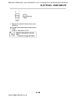
NOTE:
When installing the throttle position sensor (for
throttle valves), adjust its angle properly. Refer
to "ADJUSTING THE THROTTLE POSITION
SENSOR (FOR THROTTLE VALVES)" on
page 7-6.
EAS28370
CHECKING THE AIR INDUCTION SYSTEM
SOLENOID
1. Check:
• Air induction system solenoid resistance
Out of specification
→
Replace.
▼▼▼▼▼▼▼▼▼▼▼▼▼▼▼▼▼▼▼▼▼▼▼▼▼▼▼▼▼▼
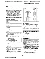
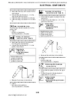
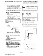
a. Disconnect the air induction system sole-
noid coupler from the air induction system
solenoid.
b. Connect the pocket tester (
Ω
×
1) to the air
induction system solenoid terminal as
shown.
c. Measure the air induction system solenoid
resistance.
▲▲▲▲▲▲▲▲▲▲▲▲▲▲▲▲▲▲▲▲▲▲▲▲▲▲▲▲▲▲
EAS28380
CHECKING THE ATMOSPHERIC PRES-
SURE SENSOR
1. Check:
• Atmospheric pressure sensor output volt-
age
Out of specification
→
Replace.
▼▼▼▼▼▼▼▼▼▼▼▼▼▼▼▼▼▼▼▼▼▼▼▼▼▼▼▼▼▼
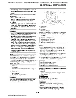
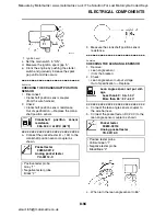
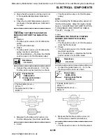
a. Connect the pocket tester (DC 20 V) to the
atmospheric pressure sensor coupler (wire
harness side) as shown.
b. Set the main switch to “ON”.
c. Measure the atmospheric pressure sensor
output voltage.
▲▲▲▲▲▲▲▲▲▲▲▲▲▲▲▲▲▲▲▲▲▲▲▲▲▲▲▲▲▲
EAS28390
CHECKING THE CYLINDER IDENTIFICA-
TION SENSOR
1. Check:
• Cylinder identification sensor output volt-
age
Out of specification
→
Replace.
▼▼▼▼▼▼▼▼▼▼▼▼▼▼▼▼▼▼▼▼▼▼▼▼▼▼▼▼▼▼
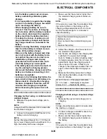
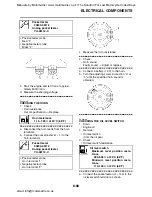
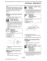
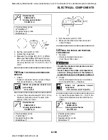
a. Connect the pocket tester (DC 20 V) to the
cylinder identification sensor coupler (wire
harness side) as shown.
Solenoid resistance
18–22
Ω
at 20
°
C (68
°
F)
Pocket tester
90890-03112
Analog pocket tester
YU-03112-C
• Positive tester probe
Brown/Red “1”
• Negative tester probe
Red/White “2”
Atmospheric pressure sensor
resistance
3.75–4.25 V
Pocket tester
90890-03112
Analog pocket tester
YU-03112-C
• Positive tester probe
Pink “1”
• Negative tester probe
Black/Blue “2”
Cylinder identification sensor
output voltage
When sensor is on
4.8 V or more
When sensor is off
4.8 V or less
Manuals by Motomatrix / www.motomatrix.co.uk / The Solution For Lost Motorcycle Coded Keys
email: [email protected]


