CRANKSHAFT
5-81
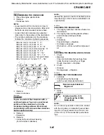
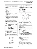
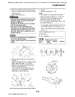
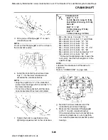
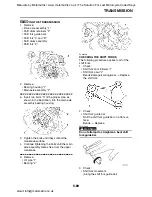
d. Put a piece of Plastigauge® “2” on each
crankshaft journal.
NOTE:
Do not put the Plastigauge® over the oil hole in
the crankshaft journal.
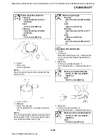
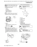
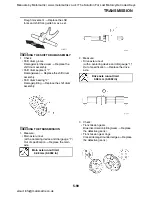
e. Install the crankshaft journal lower bear-
ings “1” into the lower crankcase and
assemble the crankcase halves.
NOTE:
• Align the projections “a” of the crankshaft
journal lower bearings with the notches “b” in
the lower crankcase.
• Do not move the crankshaft until the clear-
ance measurement has been completed.
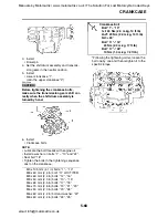
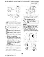
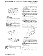
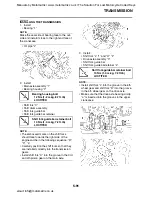
f.
Tighten the bolts to specification in the
tightening sequence cast on the crankcase.
M9 x 105 mm (4.1 in) bolts: “1”–“10”
M8 x 60 mm (2.4 in) bolt: “11” LOCTITE®
M8 x 60 mm (2.4 in) bolts: “12”, “16”
M8 x 50 mm (2.0 in) bolts: “13”–“15”
M6 x 65 mm (2.5 in) bolts: “17”, “18”
M6 x 70 mm (2.8 in) bolts: “19”, “21”, “23”
M6 x 50 mm (2.0 in) bolts: “20”, “26”
M6 x 60 mm (2.4 in) bolt and washer: “22”
M6 x 60 mm (2.4 in) bolts: “24”, “25”
* Following the tightening order, loosen the
bolt one by one and then retighten it to the
specific torque.
NOTE:
Lubricate the crankcase bolt threads with
engine oil.
Refer to "CRANKCASE" on page 5-65.
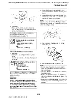
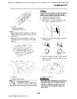
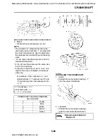
g. Remove the lower crankcase and the
crankshaft journal lower bearings.
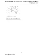
h. Measure the compressed Plastigauge®
width “c” on each crankshaft journal.
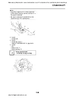
If the crankshaft-journal-to-crankshaft-jour-
nal bearing clearance is out of specifica-
tion, select replacement crankshaft journal
bearings.
Crankcase bolt
Bolt “1”–“10”
1st: 20 Nm (2.0 m·kg, 14 ft·lb)
2nd: 20 Nm (2.0 m·kg, 14 ft·lb)
3rd: +60
°
Bolt “11”–“16”
24 Nm (2.4m·kg, 17 ft·lb)
Bolt “17”–“26”
10 Nm (1.0m·kg, 7.2 ft·lb)
Manuals by Motomatrix / www.motomatrix.co.uk / The Solution For Lost Motorcycle Coded Keys
email: [email protected]

