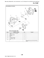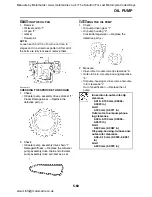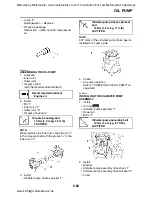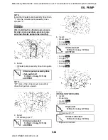
CLUTCH
5-52
NOTE:
Assemble the friction plates and clutch plates
according to the installation order.
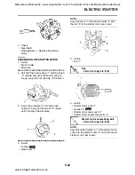
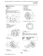
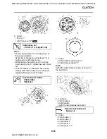
7. Install:
• Friction plate 1 “1”
NOTE:
Install the last friction plate shifting half phase
with the ø2 punch mark “2”.
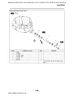
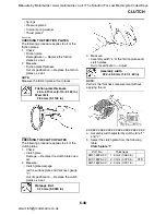
8. Install:
• Bearing
• Pull rod
• Pressure plate 1 “1”
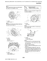
9. Install:
• Clutch springs
• Clutch spring bolts “1”
NOTE:
Tighten the clutch spring bolts in stages and in
a crisscross pattern.
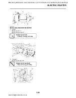
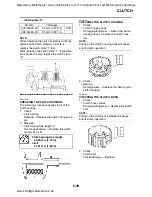
10. Install:
• Push lever
NOTE:
Install the push lever with the “h” mark facing
toward upper side.
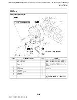
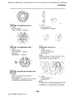
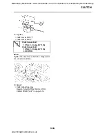
11. Install:
• Clutch cover
• Clutch cover gasket
NOTE:
• Install the push rod so that the teeth a face
towards the rear of the vehicle. Then, install
the clutch cover.
• Apply oil onto the bearing.
• Apply molybdenum disulfide grease onto the
push rod.
• When installing the clutch cover, push the
push lever and check that the punch mark “a”
on the push lever aligns with the mark “b” on
the clutch cover. Make sure that the push rod
teeth and push lever shaft pinion gear are
engaged.
Clutch spring bolt
10 Nm (1.0 m·kg, 7.2 ft·lb)
Manuals by Motomatrix / www.motomatrix.co.uk / The Solution For Lost Motorcycle Coded Keys
email: [email protected]

