ENGINE
3-5
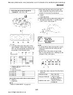
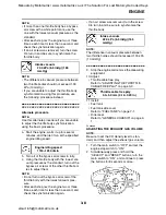
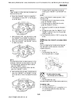
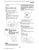
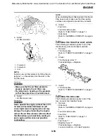
d. To measure the valve clearances of the
other cylinders, starting with cylinder #1 at
TDC, turn the crankshaft counterclockwise
as specified in the following table.
▲▲▲▲▲▲▲▲▲▲▲▲▲▲▲▲▲▲▲▲▲▲▲▲▲▲▲▲▲▲
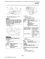
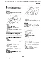
5. Remove:
• Camshafts
NOTE:
• Refer to "CAMSHAFTS" on page 5-9.
• When removing the timing chain and cam-
shafts, fasten the timing chain with a wire to
retrieve it if it falls into the crankcase.
6. Adjust:
• Valve clearance
▼▼▼▼▼▼▼▼▼▼▼▼▼▼▼▼▼▼▼▼▼▼▼▼▼▼▼▼▼▼
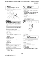
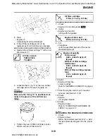
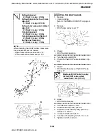
a. Remove the valve lifter “1” and the valve
pad “2” with a valve lapper “3”.
NOTE:
• Cover the timing chain opening with a rag to
prevent the valve pad from falling into the
crankcase.
• Make a note of the position of each valve
lifter “1” and valve pad “2” so that they can be
installed in the correct place.
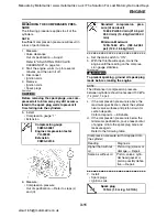
b. Select the proper valve pad from the follow-
ing table.
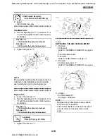
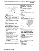
Valve clearance measuring sequence
Cylinder #1
→
#2
→
#4
→
#3
A. Front
A. Degrees that the crankshaft is turned
counterclockwise
B. Cylinder
C. Combustion cycle
Cylinder #2
180
°
Cylinder #4
360
°
Cylinder #3
540
°
Valve lapper
90890-04101
Valve lapping tool
YM-A8998
Valve pad range
Nos. 156–240
Valve pad thickness
1.56–2.40 mm
(0.0614–0.0945 in)
Available valve pads
25 thicknesses in
0.05 mm (0.002 in)
increments
Manuals by Motomatrix / www.motomatrix.co.uk / The Solution For Lost Motorcycle Coded Keys
email: [email protected]

