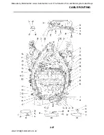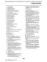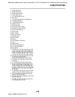
CABLE ROUTING
2-42
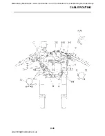
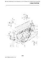
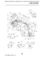
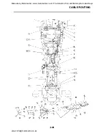
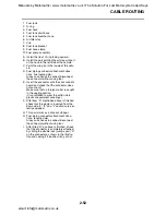
1. Right handlebar switch lead
2. Clutch cable
3. Main switch lead
4. Left handlebar switch lead
5. Horn lead
6. Horn
7. Throttle cables
8. Brake hose
9. Throttle cable (return side)
10.Throttle cable (pull side)
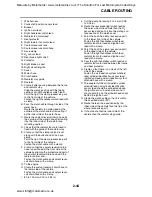
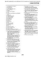
A. Route the clutch cable so as to get along
the front side of the main switch after pass-
ing it through the guide.
B. Pass the main switch lead through the
guide wire.
C. Pass the left handlebar switch lead through
the guide wire.
D. Pass the clutch switch lead through outside
of the left handlebar switch lead.
E. Point the tip of the band (excessive part) to
the left side of the vehicle and cut the sur-
plus section.
F. Clamp the section between 0 and 20 mm
(0 and 0.79 in) from the split of the under
bracket.
G. Clamp the leads inside the front fork of the
vehicle. Point the exit of the horn lead to
the left front fork side.
H. Fit in the clamp from the inner side to the
outer side of the vehicle so that the return
side is positioned upper and the pull side is
lower at the upper side of the vehicle above
the brake hose.
I. 0 to 30 mm (0 to 1.18 in)
J. Route two throttle cables behind the brake
hose, pass between the inside of the under
bracket’s upper side front fork.
K. 20 to 40 mm (0.8 to 1.6 in)
L. Point the tip of the band (excessive part) to
the right side of the vehicle and cut the sur-
plus section.
M. Pass the left handlebar switch lead through
upper side of the steering damper bracket.
N. Cut the clamp tip leaving 2 to 4 mm (0.08
to 0.16 in).
O. Outside of the vehicle.
P. Inside of the vehicle.
Manuals by Motomatrix / www.motomatrix.co.uk / The Solution For Lost Motorcycle Coded Keys
email: [email protected]


