5-46 Image Optimization
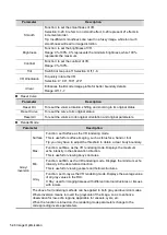
Parameter
Description
Smooth
Function: to set the smoothness of VR.
Selection: 0-20. 0 refers to no smooth effect, 0-20 represent 21 effects in
incremental order.
Tip: Insufficient smoothness can result in a fuzzy image, while too much
smoothness will lead to image distortion.
Brightness
Function: to set the brightness of VR.
Range: 0%-100%. 0% represents the minimum brightness, while 100%
represents the maximum.
Contrast
Function: to set the contrast of VR.
Range: 0%-100%.
Tint
Switch tint map on/off. Selection: Off, 1-8.
VR Orientation
To quickly rotate the VR.
Selection: 0°, 90°, 180°, 270°.
iClear
Enhances the B mode image profile for better boundary details.
Range: Off, 1-7.
Reset Curve
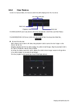
Parameter
Description
Reset Ori.
To reset the volume rotation, shifting and zooming to its original status.
Reset Curve
To reset the curve to its original status.
Reset All
To reset the volume to its original orientation and original parameters.
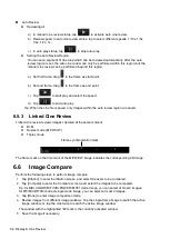
Render Mode
Parameter
Description
Gray/
Inversion
Surface
Function: set Surface as the VR rendering mode.
This is useful for surface imaging, such as fetus face, hand or foot.
Tip: you may have to adjust the threshold to obtain a clear body boundary.
Max.
Function: set Max. as the VR rendering mode. Displays the maximum
echo intensity in the observation direction.
This is useful for viewing bony structures.
Min.
Function: set Min. as the VR rendering mode. Displays the minimum echo
intensity in the observation direction.
This is useful for viewing vessels and hollow structures.
X-ray
Function: set X-ray as the VR rendering mode. Displays the average value
of all gray values in the ROI.
X Ray: used for imaging tissues with different internal structures or tissues
with tumors.
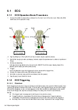
The above four rendering methods can be applied to both gray and inversion modes.
Where inversion means to invert the grayscale of the image, so as to enhance
observation for low-echo regions, applicable for vessels, cysts, etc.
When the function is turned on, the rendering mode parameters change to the
corresponding inverse parameters.
Summary of Contents for TE5
Page 1: ...TE7 TE5 Diagnostic Ultrasound System Operator s Manual Basic Volume ...
Page 2: ......
Page 6: ......
Page 12: ......
Page 24: ......
Page 36: ......
Page 54: ......
Page 110: ......
Page 115: ...Display Cine Review 6 5 6 Tap Return on the screen or tap Freeze to exit image compare ...
Page 120: ......
Page 124: ......
Page 156: ......
Page 174: ......
Page 192: ...12 18 Setup Select Advanced and do as follows Select MAPS and do as follows ...
Page 202: ...13 2 Probes and Biopsy C5 2s L12 4s L7 3s P4 2s L14 6s C11 3s L14 6Ns V11 3Ws P7 3Ts 7LT4s ...
Page 226: ...13 26 Probes and Biopsy NGB 034 NGB 035 ...
Page 250: ......
Page 272: ......
Page 276: ...A 4 Wireless LAN Tap Add Manually create a network profile to set ...
Page 282: ......
Page 318: ......
Page 322: ......
Page 323: ...P N 046 006959 07 1 0 ...

