8-2 Physiological Signal
8.1
ECG
8.1.1 ECG Operation Basic Procedures
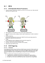
1. Connect the ECG module to the serial port on the rear cover of the main unit. Place the ECG
electrodes on the patient’s body.
2. Tap the [Physio] on the right of the screen to enter physio operation status.
3. Switch the imaging modes and display formats. Adjust the parameters to obtain an optimized
image.
4. Parameter adjusting
In image menu, tap [ECG] in the menu to turn ON/OFF the ECG wave display. Adjust the
[Speed], [ECG Gain], [Position] and [Invert]
5. Trigger:
Touch Trig Mode to open the triggering function and sect the trigger time.
6. Freeze the image and review the image and waves.
7. Exit ECG mode, and remove ECG electrodes from the patient.
8. Tap [Physio] to exit the ECG mode.
8.1.2 ECG Triggering
8.1.2.1 Overview
ECG triggering means that image scanning is activated at some time points of ECG signals, thus
obtaining B images at these time points. In most cases, the triggered image are 2D-mode image.
When ECG triggering occurs, a mark appears on the ECG waveform, indicating the time points
when the B images are captured (corresponding to the delay time from R curve started).
NOTE:
The trigger mark is displayed in both freeze mode and live mode.
Trigger function is unavailable if the ECG trace is disappeared. Trigger function is
unavailable if the ECG trace is disappeared. Only the live 2D image can be triggered.
No delay time or time interval shall less than the time required to scan a single image.
IEC standard
AHA standard
Red
Yellow
Green
Black
Black
Green
Red
White
Left
Right
Left
Right
Summary of Contents for TE5
Page 1: ...TE7 TE5 Diagnostic Ultrasound System Operator s Manual Basic Volume ...
Page 2: ......
Page 6: ......
Page 12: ......
Page 24: ......
Page 36: ......
Page 54: ......
Page 110: ......
Page 115: ...Display Cine Review 6 5 6 Tap Return on the screen or tap Freeze to exit image compare ...
Page 120: ......
Page 124: ......
Page 156: ......
Page 174: ......
Page 192: ...12 18 Setup Select Advanced and do as follows Select MAPS and do as follows ...
Page 202: ...13 2 Probes and Biopsy C5 2s L12 4s L7 3s P4 2s L14 6s C11 3s L14 6Ns V11 3Ws P7 3Ts 7LT4s ...
Page 226: ...13 26 Probes and Biopsy NGB 034 NGB 035 ...
Page 250: ......
Page 272: ......
Page 276: ...A 4 Wireless LAN Tap Add Manually create a network profile to set ...
Page 282: ......
Page 318: ......
Page 322: ......
Page 323: ...P N 046 006959 07 1 0 ...

