13-30 Probes and Biopsy
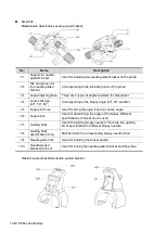
NGB-010
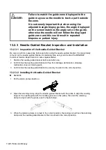
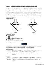
1. Put on the probe cover.
2. Hold the probe by one hand, select proper needle-guided bracket, and hold it with the other
hand, and align the grooves of the needle-guided bracket with the tabs of the probe, then push
the needle-guided bracket forward, making the grooves of the needle-guided bracket to match
with the tabs of the probe. Set the needle-guided bracket at the desired position, turn tightly
the knob of fixing needle-guided bracket to fix the needle-guided bracket.
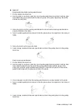
3. Check manually to confirm the needle-guided bracket is securely installed on the probe.
4. Select a proper guiding block and push it into the groove above the support of needle-guided
bracket, then turn tightly the knob of fixing the guiding block to fix the guiding block on the
support of needle-guided bracket.
5. Insert a biopsy needle with the same specification as that of the guiding block into the hole of
the guiding block.
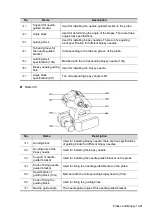
NGB-011
1. Connect the locating groove on the clamp with the two raised edges on the probe head and
align the locating pit of the clamp with the convex point on the probe head.
2. Turn the grip knob at the tail of the needle-guided bracket tightly.
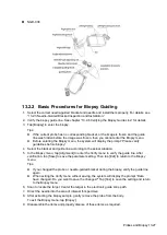
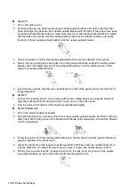
NGB-015/NGB-022
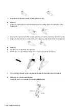
1. Put on the sterile transducer sheath.
2. Hold the transducer by one hand, select the proper needle-guided bracket, and hold it with the
other hand. Match the groove of the bracket with the tab of the transducer. Amount the bracket
onto the transducer.
3. Screw the pinch nut of the needle-guided bracket to confirm that the needle-guided bracket is
properly installed on the transducer.
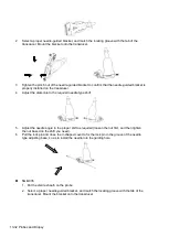
4. Adjust the dial scale to the required needle type shift, and then screw the needle fixing nut to
lock the dial scale. (To adjust the dial scale you have to loosen the needle fixing nut first.)
5. Pull the lock pin and close the V-shaped cover to fix the lock pin in the groove of the needle
type adjusting base, so as to install the needle into the guiding hole.
Summary of Contents for TE5
Page 1: ...TE7 TE5 Diagnostic Ultrasound System Operator s Manual Basic Volume ...
Page 2: ......
Page 6: ......
Page 12: ......
Page 24: ......
Page 36: ......
Page 54: ......
Page 110: ......
Page 115: ...Display Cine Review 6 5 6 Tap Return on the screen or tap Freeze to exit image compare ...
Page 120: ......
Page 124: ......
Page 156: ......
Page 174: ......
Page 192: ...12 18 Setup Select Advanced and do as follows Select MAPS and do as follows ...
Page 202: ...13 2 Probes and Biopsy C5 2s L12 4s L7 3s P4 2s L14 6s C11 3s L14 6Ns V11 3Ws P7 3Ts 7LT4s ...
Page 226: ...13 26 Probes and Biopsy NGB 034 NGB 035 ...
Page 250: ......
Page 272: ......
Page 276: ...A 4 Wireless LAN Tap Add Manually create a network profile to set ...
Page 282: ......
Page 318: ......
Page 322: ......
Page 323: ...P N 046 006959 07 1 0 ...


