5-10 Image Optimization
5.3
M Mode Image Optimization
5.3.1 Basic Procedures for M Mode Imaging
1. Select a high-quality image during B mode scanning, and adjust to position the area of interest in
the center of the B mode image.
2. Tap [M] on the right side of the operating panel to enter M sampling line status, and drag the
sampling line to the desired position.
3. Tap [M]/ [Update] or double-click the sampling line to enter M mode. You can then observe the
tissue motion along with the anatomical images of B mode. During the scanning process, you
can also adjust the sampling line accordingly when necessary.
4. Adjust the image parameters to obtain optimized images.
5. Perform other operations (e.g., measurement and calculation) if necessary.
5.3.2 M Mode Image Parameters
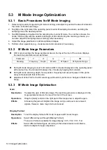
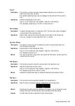
In M mode scanning, the image parameter area in the top-left corner of the screen displays
the real-time parameter values as follows:
Parameter
F
D
G
V
DR
Meaning
Frequency
Depth
M Gain
M Speed
M Dynamic Range
During M mode imaging, menus for B mode and M mode are displayed on the operating panel
at the same time. You can switch between the 2 modes by tapping the mode tab.
During M mode scanning, depth, focus position, frequency and acoustic power of the probe
are synchronous with that of B mode.
Adjustment of the TGC to the B mode image will lead to synchronous changes in the M mode
image.
5.3.3 M Mode Image Optimization
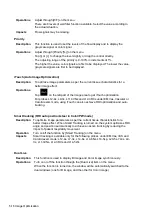
Gain
Description
To adjust the gain of M mode image. The real-time gain value is displayed in the
image parameter area in the top-left corner of the screen.
Operations
Drag the [Gain] control on the right part of the image area to adjust the gain.
Effects
Increasing the gain will brighten the image and you will see more received
signals. However, noise may also be increased.
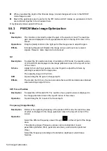
Display Format
Description
To set the display format of M mode images and B mode images.
Operations
Select different layout through [Display Format].
There are 4 formats available for image display: V2:3, V3:2, V3:1, Full.
Effects
Select different format types according to the actual situation and obtain a
desired analysis through comparison.
Summary of Contents for TE5
Page 1: ...TE7 TE5 Diagnostic Ultrasound System Operator s Manual Basic Volume ...
Page 2: ......
Page 6: ......
Page 12: ......
Page 24: ......
Page 36: ......
Page 54: ......
Page 110: ......
Page 115: ...Display Cine Review 6 5 6 Tap Return on the screen or tap Freeze to exit image compare ...
Page 120: ......
Page 124: ......
Page 156: ......
Page 174: ......
Page 192: ...12 18 Setup Select Advanced and do as follows Select MAPS and do as follows ...
Page 202: ...13 2 Probes and Biopsy C5 2s L12 4s L7 3s P4 2s L14 6s C11 3s L14 6Ns V11 3Ws P7 3Ts 7LT4s ...
Page 226: ...13 26 Probes and Biopsy NGB 034 NGB 035 ...
Page 250: ......
Page 272: ......
Page 276: ...A 4 Wireless LAN Tap Add Manually create a network profile to set ...
Page 282: ......
Page 318: ......
Page 322: ......
Page 323: ...P N 046 006959 07 1 0 ...


