Image Optimization 5-43
MPR Viewing
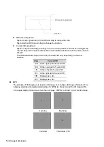
In the actual display, different colors for the window box and the section line are used to identify
the MPR A, B and C.
Window A is blue, and the lines (representing MPR A) displayed in the other two windows
are also blue.
Window B is yellow, and the lines (representing MPR B) displayed in the other two
windows are also yellow.
Window C is orange, and the lines (representing MPR C) displayed in the other two
windows are also orange.
The positions of the other two MPRs are indicated in the selected plane by color described above.
Display Format
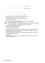
Tap to select the display format of VR and MPR images: [Single], [Quad] and [A4:1].
MPR Only
Tap [MPR Only] to display MPR only. The adjustable image parameters are changed to MPR
parameters automatically.
Only A, B and C MPR are displayed, and VR is not displayed.
Sectional A
Sectional B
Sectional C
Summary of Contents for TE5
Page 1: ...TE7 TE5 Diagnostic Ultrasound System Operator s Manual Basic Volume ...
Page 2: ......
Page 6: ......
Page 12: ......
Page 24: ......
Page 36: ......
Page 54: ......
Page 110: ......
Page 115: ...Display Cine Review 6 5 6 Tap Return on the screen or tap Freeze to exit image compare ...
Page 120: ......
Page 124: ......
Page 156: ......
Page 174: ......
Page 192: ...12 18 Setup Select Advanced and do as follows Select MAPS and do as follows ...
Page 202: ...13 2 Probes and Biopsy C5 2s L12 4s L7 3s P4 2s L14 6s C11 3s L14 6Ns V11 3Ws P7 3Ts 7LT4s ...
Page 226: ...13 26 Probes and Biopsy NGB 034 NGB 035 ...
Page 250: ......
Page 272: ......
Page 276: ...A 4 Wireless LAN Tap Add Manually create a network profile to set ...
Page 282: ......
Page 318: ......
Page 322: ......
Page 323: ...P N 046 006959 07 1 0 ...

