Probes and Biopsy 13-37
13.2.5 iNeedle (Needle Visualization Enhancement)
During a biopsy, the metal needle attached to the probe pierces the tissue at a certain angle. Due
to the needle's acoustic impedance, the ultrasonic beam cannot penetrate the metal needle and a
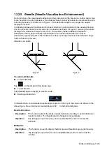
reflecting boundary is formed. As in Figure 1, if the deflection angle is very large, the needle
display is not clear.
In deflected ultrasound transmission, the beam direction is perpendicular to the needle direction
and the reflection direction is the same as the needle, as shown in Figure 2, meaning the needle
display in the ultrasound image is very clear. The system provides additional deflection
transmission that is approximately perpendicular to the metal needle when the normal
transmission (perpendicular to the transducer surface) is being processed. The deflection angle
can be chosen by the user.
iNeedle is an option.
Figure 1
Figure 2
To enter/exit iNeedle
To enter iNeedle
Tap
on the left part of the image area.
To exit iNeedle
Tap [iNeedle] again or tap [B] to enter B mode.
Best angle indication
In iNeedle mode, recommended needle angle is given on the top of the screen. As shown in the
above figure, the current recommended angle is 50
°
to the horizontal plane.
Needle Direction
Description
This function adjusts the biopsy needle direction according to actual direction of
needle insertion. The iNeedle region changes correspondingly.
Operation
Tap [Image] to open the menu, and use [Needle Dir.] control to select the
direction.
B/iNeedle
Description
This function is used to display the B image and iNeedle image synchronously.
Operation
Tap [Image] to open the menu and use [B/iNeedle] control to turn on/off the
function.
Summary of Contents for TE5
Page 1: ...TE7 TE5 Diagnostic Ultrasound System Operator s Manual Basic Volume ...
Page 2: ......
Page 6: ......
Page 12: ......
Page 24: ......
Page 36: ......
Page 54: ......
Page 110: ......
Page 115: ...Display Cine Review 6 5 6 Tap Return on the screen or tap Freeze to exit image compare ...
Page 120: ......
Page 124: ......
Page 156: ......
Page 174: ......
Page 192: ...12 18 Setup Select Advanced and do as follows Select MAPS and do as follows ...
Page 202: ...13 2 Probes and Biopsy C5 2s L12 4s L7 3s P4 2s L14 6s C11 3s L14 6Ns V11 3Ws P7 3Ts 7LT4s ...
Page 226: ...13 26 Probes and Biopsy NGB 034 NGB 035 ...
Page 250: ......
Page 272: ......
Page 276: ...A 4 Wireless LAN Tap Add Manually create a network profile to set ...
Page 282: ......
Page 318: ......
Page 322: ......
Page 323: ...P N 046 006959 07 1 0 ...


