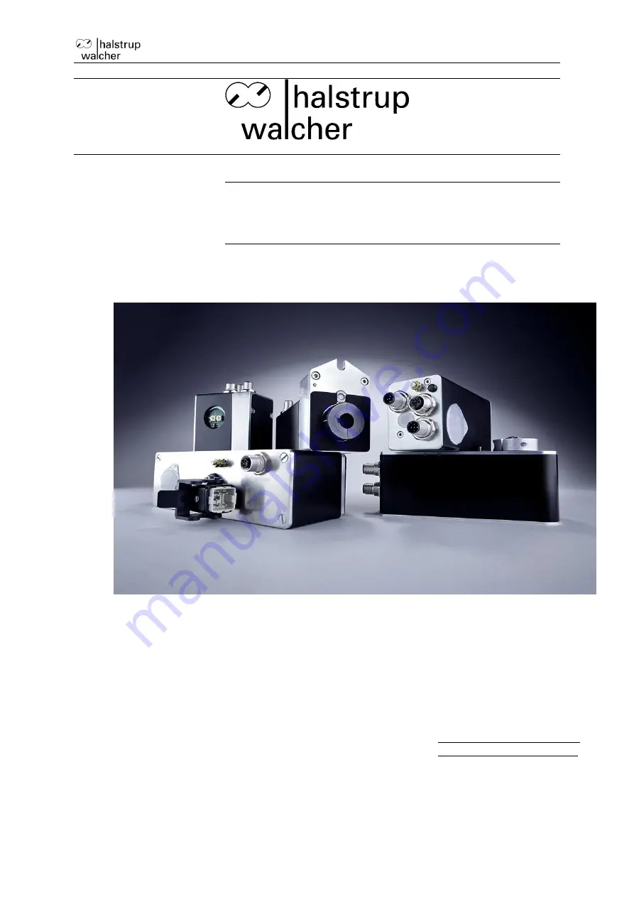
background image


Instruction Manual PSx3xxPL 


Document 7100.006754 


Original Instruction Manual 
PSx3xxPL-STO 


halstrup-walcher GmbH 
Stegener Straße 10 
 
D-79199 Kirchzarten 
 
 
Tel.:  

+49 (0) 76 61/39 63-0 

Fax:  

+49 (0) 76 61/39 63-99 

 
E-Mail:  

[email protected] 

Internet:  

www.halstrup-walcher.com 


Summary of Contents for PS-3 Series

Page 1: ...ument 7100 006754 Original Instruction Manual PSx3xxPL STO halstrup walcher GmbH Stegener Straße 10 D 79199 Kirchzarten Tel 49 0 76 61 39 63 0 Fax 49 0 76 61 39 63 99 E Mail info halstrup walcher com Internet www halstrup walcher com ...

Page 2: ... T STO CE with Test pulses Y STO NRTL without Test pulse Z STO NRTL with Test pulses 54 IP 54 65 IP 65 68 IP 68 Positioning System Stainless PSS Positioning System Washable PSW Remarks Other shaft diameters possible as special design Labelling 3xx XX So 3 always via an extra connector Example for a device variant PSE335 14 PL Z 0 Z 65 PSE 335 14 PL Z 0 Z 65 A B C D E F G Revision Overview Version ...

Page 3: ...throughout the lifecycle of the devices It must be provided to any individuals who assume responsibility for operating the device at a later date It must include any supplementary materials provided by the manufacturer The manufacturer reserves the right to continue developing this device model without documenting such development in each individual case The manufacturer will be happy to determine...

Page 4: ...ect dictionary 15 2 9 2 Table of rated speed and torque values for various models of gears 22 2 9 3 PDO definition 23 2 9 4 Detailed description of the status bits 24 2 9 5 Detailed description of control bits 26 3 Sequence of positioning 28 3 1 Positioning run with loop 28 3 2 Positioning run without loop 29 4 Specials 30 4 1 Speed acceleration and deceleration 30 4 2 Maximum starting torque and ...

Page 5: ...ning with the adjustment facility 41 4 13 Devices with optional snap brake 41 4 14 Reference runs 42 4 15 Reverse drive 42 4 16 Safe Torque Off 43 5 Technical Data 44 5 1 Ambient conditions 44 5 2 Electrical Data 44 5 3 STO Data 45 5 4 Physical data 45 6 Certificate of Conformity 46 ...

Page 6: ...p Assembly and the electrical connections should only be handled by professionals They should be given proper training and be authorised by the operator of the facility The device may only be operated by appropriately trained individuals who have been authorized by the operator of the facility Specific safety precautions are given in individual sections of this manual 1 3 Troubleshooting maintenan...

Page 7: ...ential hazard that could lead to bodily injury up to and including death if the corresponding instructions are not followed CAUTION This warns you of a potential hazard that could lead to significant property damage if corresponding instructions are not followed INFORMATION This indicates that the corresponding information is important for operating the device properly Caution This indicates possi...

Page 8: ...me stands for a number in the range 10 999 Safe Torque Off This device variant STO contains functions of the functional safety Safe Torque Off The specific information about the safety function can be found in the safety manual Document No 7100 006654 When using the STO function the conditions and instructions given in the safety manual must be observed in order to achieve the required level of sa...

Page 9: ...h higher torques from 10 Nm Here the force connection is made via a feather key DIN 6885 A5x5x12 The clamping ring is not freely rotatable but consists of two halves the fixed part of the hollow shaft and the loose clamping clamp The keyway is located in the half that is fixed to the output shaft When sliding onto the shaft to be driven with the key inserted its angular position must be aligned wi...

Page 10: ... can damage the output shaft For versions with brake it is essential to observe the instructions in sections 4 13 2 4 Powering the device There is one common power supply for the motor and control unit of the positioning system It is recommended to use SELV or PELV power supplies For the combined motor and control power use a single fuse with max 3 5 A for each PSx3xx It is strongly recommended to...

Page 11: ...o the PSW housing during cooldown use a special cable with an airtube for pressure balancing of your PSW 2 5 2 Round socket for bus Port 1 and Port 2 connector pattern external top view assignment type 1 TD WH GN white green 2 RD WH OG white orange 3 TD GN green 4 RD OG orange M12 D cod 4 pol Due to the use of 4 pin sockets only four wire cables should be used 2 5 3 1 Hybrid bushing for supply bus...

Page 12: ...under the transparent sealing plug P1 P2 green Link Act LEDs for ports 1 and 2 BS BE Powerlink STATUS and ERROR LEDs green red see Powerlink spec V_Motor The LED is illuminated yellow when power is available to the motor Switch configurations PSx30x PSx31x 8 PSx31x 14 PSx33x PSx32x PSE31xx PSE34xx Meaning of the LEDs 1 Each of the ports P1 P2 has an associated green LED for the Link and the Activi...

Page 13: ...on does not need to be altered If a manual run is transmitted during a positioning run the positioning run will be aborted speed will be reduced to that of a manual run and the device proceeds with the manual run The following sequence of steps is also possible Starting situation release has not been set Transfer target value PDO with control word 0x04 and desired target value OR PDO with control ...

Page 14: ...the address switch to 98 3 Switch on the device control and motor supply voltage 4 The yellow LED now flashes at 10Hz for 10 seconds If during this time the address is set to 99 the drive will set all parameters to the factory settings save them and move the axle to the centre position 5 Set the address switch to 00 to complete the delivery state 6 Switch off the device The 10 second period is end...

Page 15: ...erlink drives when being read the string PSx3xxIE PL is given back R Identity 1018 sub index 0 quantity of indexes 4 sub 1 Vendor ID 0x000002D8 sub 2 Product code sub 3 Revision number 0x00010000 sub 4 Serial number 8 bit 32 bit 32 bit 32 bit 32 bit 4 R R R R R Receive PDO 1 communi cation parameter 1400 sub index 0 quantity of indexes 2 sub 1 Node ID 0 sub 2 Mapping Version 0 8 bit 0 0 8 bit 8 bi...

Page 16: ...ator and denominator 0 1000 16 bit yes 0 R W positioning window 2006 permissible difference between target and actual values for position reached bit value in 1 100 mm for a 4mm spindle and default settings of numerator and denominator The maximum value that can be set changes according to the same factor as the resolution Changes only possible when at standstill 1 100 16 bit yes 2 R W position sc...

Page 17: ...time elapsed until speed falls below rpm limit for aborting run 201B value in msec 50 500 16 bit yes 200 R W acceleration 201C value in rpm per sec see table 2 9 2 16 bit yes see table 2 9 2 R W deceleration 201D value in rpm per sec see table 2 9 2 16 bit yes see table 2 9 2 R W length of loop 201F minimum number of increments which the drive moves in a pre defined direction when approaching a ta...

Page 18: ... Bit 6 drive is running Bit 7 temperature exceeded Bit 8 movement opposite loop direction Bit 9 measuring system or STO hardware error Bit 10 positioning error block Bit 11 manual displacement Bit 12 incorrect target value Bit 13 failure voltage control Bit 14 positive range limit Bit 15 negative range limit 0 FFFFh 16 bit R upper mapping end 2028 definition of the positioning range relative to th...

Page 19: ...240 16 bit yes 185 R W Umot filter 203D average time for measuring motor supply voltage value in msec 100 1000 16 bit yes 100 R W temperature limit 203E upper temperature limit in C 10 80 16 bit yes 70 R W device temperature 203F internal device temperature in C 16 bit R production date 2040 year and week of manufacturing given as an integer YYWW 16 bit R serial number 2041 serial device number 0 ...

Page 20: ...ve will continue moving to the actual target position 0x01 drive will abort any positioning 0x02 drive will move to a safe position which is defined by SDO 204A 0x03 reserved 16 bit yes 1 R W save position for connection timeout 204A drive will move to this position if a connection loss to the master has been detected and bits 1 0 of SDO 2049 are set to 0x02 the state IOPS BAD has been detected e ...

Page 21: ... are saved last by the user without saving the parameters in the EEPROM writing 1 sets the values of all parameters to the delivery state without saving the parameters in the EEPROM writing 1 saves all parameters in the EEPROM reading directly after boot 0 content of memory correct 0 content of memory incorrect reading after saving 0 saving finished successfully 0 saving is still in progress or is...

Page 22: ...0 30 0 150 50 0 300 100 0 100 35 0 200 70 0 450 150 maximum holding torque at end of run 2042 0 180 60 0 300 100 0 600 200 0 200 70 0 400 140 0 700 300 device model PSW 301 x 311 x 302 x 312 x 305 x 315 8 322 14 332 14 325 14 335 14 328 14 Name Index number Range of value Delivery State target rpm posi 2012 15 180 180 10 125 125 3 60 60 20 150 125 10 80 60 5 35 35 target rpm hand 2013 15 180 80 10...

Page 23: ...p torque 2018 100 1200 1200 250 3000 3000 100 1200 1000 250 3000 2500 180 2200 1800 maximum holding torque 202B 0 600 200 0 1250 450 0 1000 350 0 2500 900 0 1800 600 maximum holding torque at end of run 2042 0 1200 400 0 2500 900 0 500 175 0 1250 450 0 900 300 2 9 3 PDO definition 1 Receive PDO from the perspective of the PSx3xx Assignment cannot be modified Bit Byte Description corresponding SDO ...

Page 24: ...nnector is connected with Pin 1 24V This bit is reset if Pin 3 on the key connector is deconnected from Pin 1 24V Bit 3 forward jog key active This bit is set if Pin 2 on the key connector is connected with Pin 1 24V This bit is reset if Pin 2 on the key connector is deconnected from Pin 1 24V Bit 4 STO enabling active The behaviour of this bit is depending of the acknowledgement bit bit 14 in the...

Page 25: ...a positioning run or a manual run in opposite of the loop direction when commanding a positioning run or a manual run when no loop is configured SDO 201F is zero This bit is reset when a transferred target position has been reached successfully in the loop direction not after a manual run Bit 9 error This bit is set if an internal problem is detected when calculating a position No run commands can...

Page 26: ...gh The status of the voltage control is always shown directly voltage control bit is set If there is no failure in the voltage control voltage control bit is reset If there is an failure in the voltage control Bit 14 15 positive negative range limit This bit is set if the limit value is reached during a manual run but not if reached during a positioning run if a limit value is modified such that t...

Page 27: ... must not be set Bit 6 Driving without a loop If this bit is set all destinations are approached directly during positioning movements regardless of the current value of SDO 201F without any loop Bit 7 Execute switch on loop 5 8 turns against loop direction and then 5 8 in loop direction with manual speed for default value of loop length SDO 201F The control word is ignored during a switch on loop...

Page 28: ...tion The target is approached directly 2 New setpoint position is smaller than the current actual position The device is moved further back by the loop length 2a and the final destination is then approached in forward motion 2b 3 New setpoint position is only slightly larger than the current actual position and previously there was no positioning movement with loop e g a manual movement In all cas...

Page 29: ...d limit SDO 2016 with a loop length 0 is not possible since the drive would have to cross the end limit for this The same applies to the lower end limit SDO 2017 with a loop length 0 3 2 Positioning run without loop The Positioning without looping mode is mainly used for moving small distances for fine corrections Each position is approached directly Any backlash in the driven spindle is NOT elimi...

Page 30: ...hievable torque is slightly higher than at the default nominal speed If small torque limits are to be used it must be considered not to use these in combination with high speed values as this can lead to unstable driving behaviour 4 3 Response of drive in case of block If during a run due to load the speed falls below the threshold parameter of 30 of the selected maximum speed SDO 201A for longer ...

Page 31: ...position not before a new run is being sent and finished successfully Deasserting the release bit and or disabling the readjustment function can completely disable the readjustment process Drives with a brake generally don t have a readjustment function 4 5 Calculating the absolute physical position The PSx3xx actuator includes an absolute measuring system with measurement range of 256 rotations I...

Page 32: ...displayed position is 2000 But the positioning range shall solely spread to the left resp bottom upper mapping end actual position 3 rotations Set SDO 2028 to 3200 Remarks 1 When calculating the upper mapping end SDO 2028 a security reserve of 3 rotations has to be kept in mind 1200 increments by default see the examples above because the highest possible position value is 3 rotations below the up...

Page 33: ...2017 drag error SDO 2005 positioning window SDO 2006 length of loop SDO 201F 8 In order to save the settings permanently in the EEPROM write 1 to SDO 204F As soon as reading of SDO 204F shows 0 the saving is finished Referencing value SDO 2004 With the help of the referencing value SDO 2004 a shift of the whole range of values can be reached The referencing process affects all transferred values i...

Page 34: ...he device has been installed the available positioning range may not be sufficient in one of the two directions The parameter upper mapping end now allows you to reduce the positioning range in one direction and increase it in the other direction 4 6 2 Shifting the positioning range upwards starting from the delivery state In the following example starting from the DS the maximum possible position...

Page 35: ... mapping end was decreased from the value 102 400 to 88 600 Consequently a higher proportion of the possible positioning range is below 51 200 and a smaller proportion above 51 200 In the extreme case the upper mapping end can be set so that the entire possible positioning range is at values 51 200 With standard scaling numerator denominator 400 i e 1 step 0 9 and referencing value 0 this special ...

Page 36: ... This is the case e g for the delivery state where numerator denominator 400 Since the upper mapping end is an integer the minimum and maximum values are obtained by rounding to the nearest integer applies only to the case numerator denominator Example Spindle with 5 mm pitch specified unit for target and actual values 1µm 1 rotation 5mm 5 000µm Number of steps per rotation 5 000 Using the formula...

Page 37: ...oning range The following section describes the procedure for determining those parameters that have an influence on the target and actual position as well as the positioning range The individual steps must be carried out in the specified order 1 Setting the direction of rotation The direction of rotation determines with which direction of rotation of the output shaft the position values increase ...

Page 38: ...0 01 mm at a spindle pitch of 4 mm The denominator factor serves as a simple means of setting the spindle pitch and resolution The numerator factor is primarily used for setting unlevel resolutions Examples Spindle pitch Resolution Numerator factor Denominator factor 4 mm 1 100 mm 400 400 1 mm 1 100 mm 400 100 2 mm 1 10 mm 400 20 Numerator and denominator factors may take on values between 1 and 1...

Page 39: ...the master cannot abort an actual run In order to generate an automatic run abort in this case there s a mechanism implemented in the drive that monitors the communication to the Powerlink Managing Node e g the bus master Three possible responses are envisaged for this case 1 If a positioning is in progress the drive should end this positioning as planned and then not start a new positioning as lo...

Page 40: ...tely A new inching movement is only possible again when both keys have been released Connecting the Jog Key Inputs The jog key inputs can be used in 2 different wiring modes Connection of potential free switches To activate the respective jog key input the 24V in the jog key plug is connected here The GND connection in the jog key plug remains unused The 24V output in the jog key plug is internall...

Page 41: ...e and thus of the drive 4 13 Devices with optional snap brake The device models PSx30x 14 PSx31x 14 PSx32x and PSx33x can be supplied with an optional snap brake This brake prevents the output shaft from turning when the power supply to the motor is removed or if the motor holding torque is too low to a maximum of the level of the nominal torque A small degree of rotation always occurs at the outp...

Page 42: ...it in the control word 3 Wait for the drive moving bit 6 in the status word is set 4 Wait for the drive has stopped and a positioning error has appeared bit 6 in the status word is cleared bit 10 is set 5 Start a manual run in the opposite direction with the same settings move a certain distance away from the hard stop in order the drive can move freely 6 Only now adjust the desired settings of th...

Page 43: ...er there might be a self locking resulting from the gear or the optional break Uncontrolled Shut down stop Stop Category 0 IEC 60204 1 Safe Torque Off 4 2 3 2 DIN EN 61800 5 2 4 The safe system state is quit autonomously when the STO input signal is no longer active For failures which are detected from the diagnostic function a quitting of the safe system state is prohibit until a power down power...

Page 44: ...E IP 54 IP 65 PSS IP 65 PSW IP 66 in operation IP 68 at standstill duty cycle Device model Duty cycle in Base time in sec PSE30xx to 33xx PSS PSW 30 20 20 300 600 600 5 2 Electrical Data nominal power output PSx30x PSx31x PSE31xx 25 W with 30 ED PSx32x PSx33x 35 W with 30 ED supply voltage 24 VDC 10 supply voltages for motor and control unit are galvanically isolated advice use regulated power sup...

Page 45: ...sation automatic loop after every positioning run may be deactivated output shaft PSE30x 8 PSE31x 8 8H9 hollow shaft with adjustable collar PSE30x 14 PSE31x 14 PSE32x PSE33x 14H7 hollow shaft with adjustable collar PSE31xx 14H7 hollow shaft with clamp and feather key PSS3xx 8 PSW3xx 8 8H9 hollow shaft with adjustable collar or 8h8 solid shaft PSS3xx 14 PSW3xx 14 14H7 hollow shaft with adjustable c...

Page 46: ...Instruction Manual PSx3xxPL 46 6 Certificate of Conformity ...

Page 47: ...Instruction Manual PSx3xxPL 47 ...

Reviews: