


ML62Q1000 Series User’s Manual
Appendix C Instruction Execution Cycle
FEUL62Q1000
C-1
Appendix C Instruction Execution Cycle
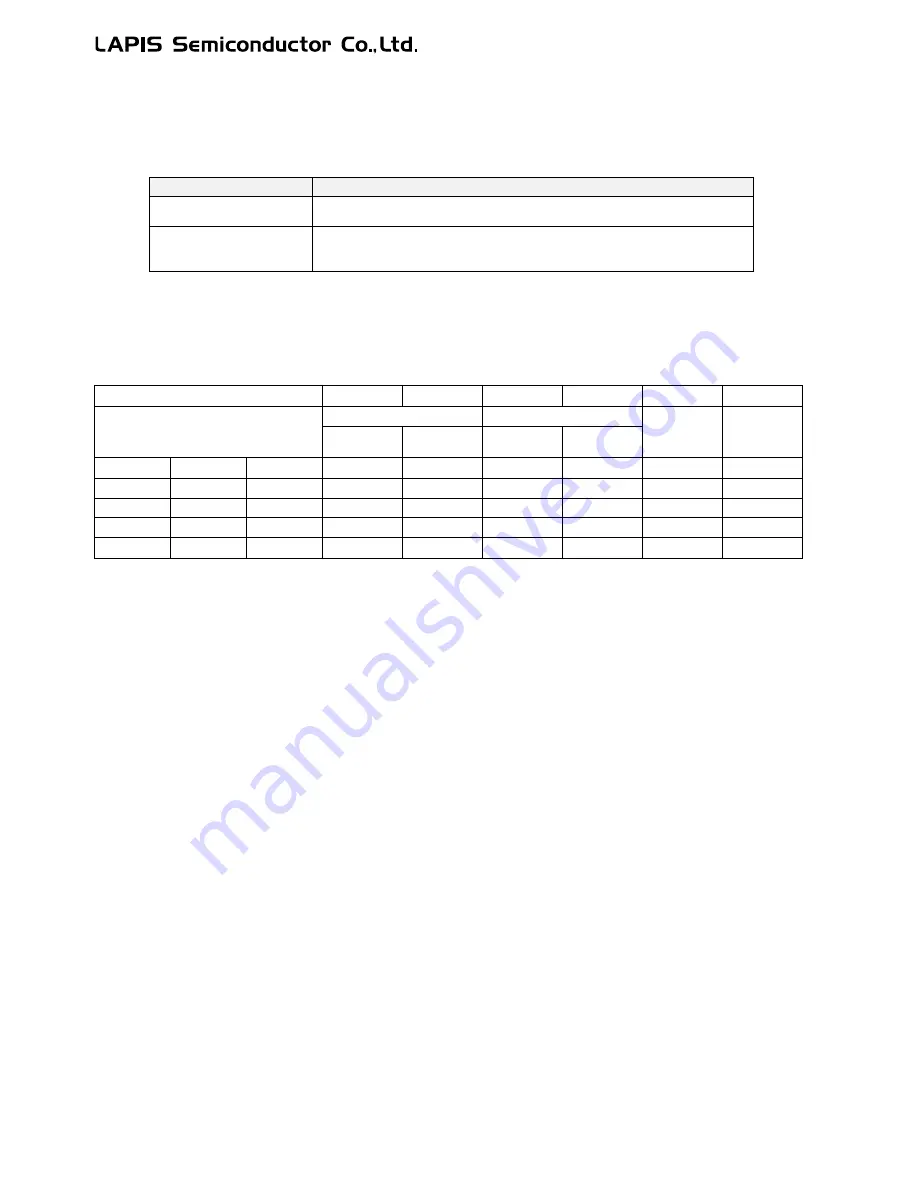
ML62Q1000 series has two CPU operating modes defined as the no wait mode and wait mode, in which there are some cases
the insturction execution cycles are different each other.
CPU Operation Mode
Description
No wait mode
There is no increase of the instruction execution cycle, as there is no wait
cycle for reading the program memory during the instruction execution.
Wait mode
There are some increases of the instruction execution cycle, as there are
some wait cycles for reading the program memory during the instruction
execution.
Tables on following pages show the all instructions of nX-U16/100 core and the execution cycles in the two CPU modes. "-"
indicates that threre is no memory access during the instruction execution. See "Example of Instruction execution cycle" for
details on how to read the table.
Example of Instruction execution cycle
(1)
(2)-1
(2)-2
(3)-1
(3)-2
(4)
(5)
Instruction
Min. execution cycle
ROM reference cycle
Effect of
DSR
access
Effect of
[EA+]
addressing
No wait
mode
Wait mode
No wait
mode
Wait mode
ADD
ER
n
ER
m
1
1
-
-
-
-
B
Cadr
-
2
6
-
-
-
1
-
ER
n
-
2
6
-
-
-
1
L
ER
n
[EA]
1
1
1
5
1
-
-
ER
n
[EA+]
1
1
1
5
1
-
[How to read the table]
(1)
These are the instructions of nX-U16/100(A35 core)
(2)
The instruction execution cycle in the case of no wait mode and wait mode.
(3)
Additional execution cycle when the instruction refers to ROM.
(4)
Additional execution cycle when the instruction reads the address allocated in segment 1 or larger.
One cycle is added in spite of the CPU operating mode.
For more details, see the section 1.3.4 "DSR Prefix Instructions" in the nX-U16/100 core instruction manual.
(5)
Additional execution effected by the instruction with the [EA+] addressig.
One cycle is added in spite of the CPU operating mode.
For more details, see the section 3.3 "Instruction Execution Times" in the nX-U16/100 core instruction manual.
Summary of Contents for ML62Q1000 Series
Page 17: ...Chapter 1 Overview...
Page 112: ...Chapter 2 CPU and Memory Space...
Page 154: ...Chapter 3 Reset Function...
Page 166: ...Chapter 4 Power Management...
Page 196: ...Chapter 5 Interrupts...
Page 248: ...Chapter 6 Clock generation Circuit...
Page 274: ...Chapter 7 Low Speed Time Base Counter...
Page 291: ...Chapter 8 16 Bit Timer...
Page 320: ...Chapter 9 Functional Timer FTM...
Page 382: ...Chapter 10 Watchdog Timer...
Page 402: ...Chapter 11 Serial Communication Unit...
Page 456: ...Chapter 12 I2 C Bus Unit...
Page 491: ...Chapter 13 I2 C Master...
Page 512: ...Chapter 14 DMA Controller...
Page 531: ...Chapter 15 Buzzer...
Page 550: ...Chapter 16 Simplified RTC...
Page 559: ...Chapter 17 GPIO...
Page 594: ...Chapter 18 External Interrupt Function...
Page 612: ...Chapter 19 CRC Generator...
Page 632: ...Chapter 20 Analog Comparator...
Page 644: ...Chapter 21 D A Converter...
Page 655: ...Chapter 22 Voltage Level Supervisor...
Page 676: ...Chapter 23 Successive Approximation Type A D Converter...
Page 709: ...Chapter 24 Regulator...
Page 714: ...Chapter 25 Flash Memory...
Page 743: ...Chapter 26 Code Option...
Page 750: ...Chapter 27 LCD Driver...
Page 788: ...Chapter 28 On Chip Debug Function...
Page 795: ...Chapter 29 Safety Function...
Page 813: ...Appendix A...
Page 881: ...Revision History...