


ML62Q1000 Series User's Manual
Chapter 11 Serial Communication Unit
FEUL62Q1000
11-53
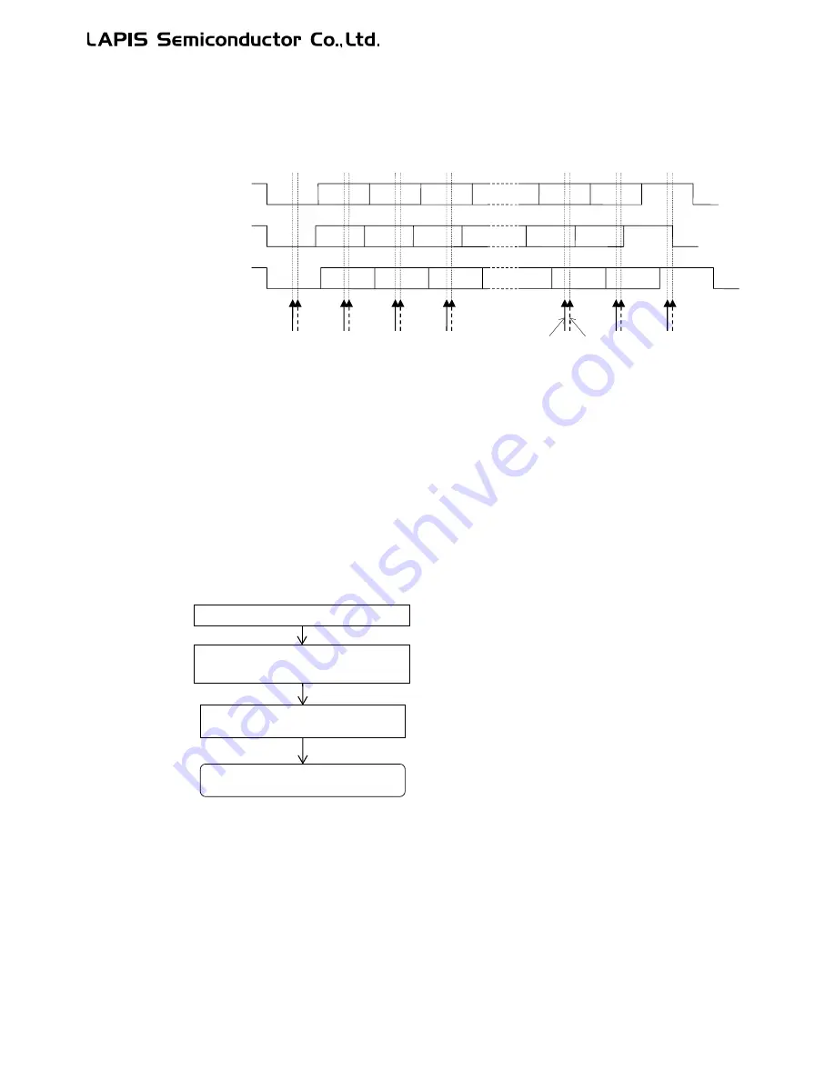
11.3.2.10 Receive Margin
If there is an error between the sender baud rate and the receiver baud rate generated by the baud rate generator, the error
accumulates until the last stop bit loading in one frame, decreasing the reception margin.
Figure 11-19 shows the baud rate errors and reception margin waveforms.
Figure 11-19 Baud Rate Errors and Reception Margin
[Note]
Ÿ
When designing the system, consider the difference of the baud rate between the transmission side and
reception side and delay of the start bit detection and adjust the baud rate in the UAn0BRT, UAn1BRT,
UAn0BRC, and UAn1BRC registers.
11.3.2.11 Note on usage of Half-duplex UART
When using the half-duplex UART and changing the transmission mode to receive mode, you must initialize and reconfigure
the channel as the receive mode after reset the channel of serial communication unit by Block Reset Control Register 2
(BRECON2). Notice that the reset by the BRECON2 register also resets other channel of the half-duplex UART.
Figure 11-20 shows the flow chart.
Figure 11-20 Flow chart for switching the transmission mode to the receive mode in Half-duplex UART mode
Sender baud rate is
slow (RXDn)
Sampling timing
UnRSS=1
UnRSS=0
Start
Start
Start
Stop
Stop
Stop
Sender baud rate is
fast (RXDn)
Ideal waveform
(RXDn)
Set the corresponding bit of the BRECON2 to "1" to
reset the target channel and then reset the bit to
"0" to release the reset.
Run the UART receive mode
Initialize and reconfigure the
channel as the receive mode
UART transmission is completed
Reset the channel by Block Reset
Control Register 2 (BRECON2).
Summary of Contents for ML62Q1000 Series
Page 17: ...Chapter 1 Overview...
Page 112: ...Chapter 2 CPU and Memory Space...
Page 154: ...Chapter 3 Reset Function...
Page 166: ...Chapter 4 Power Management...
Page 196: ...Chapter 5 Interrupts...
Page 248: ...Chapter 6 Clock generation Circuit...
Page 274: ...Chapter 7 Low Speed Time Base Counter...
Page 291: ...Chapter 8 16 Bit Timer...
Page 320: ...Chapter 9 Functional Timer FTM...
Page 382: ...Chapter 10 Watchdog Timer...
Page 402: ...Chapter 11 Serial Communication Unit...
Page 456: ...Chapter 12 I2 C Bus Unit...
Page 491: ...Chapter 13 I2 C Master...
Page 512: ...Chapter 14 DMA Controller...
Page 531: ...Chapter 15 Buzzer...
Page 550: ...Chapter 16 Simplified RTC...
Page 559: ...Chapter 17 GPIO...
Page 594: ...Chapter 18 External Interrupt Function...
Page 612: ...Chapter 19 CRC Generator...
Page 632: ...Chapter 20 Analog Comparator...
Page 644: ...Chapter 21 D A Converter...
Page 655: ...Chapter 22 Voltage Level Supervisor...
Page 676: ...Chapter 23 Successive Approximation Type A D Converter...
Page 709: ...Chapter 24 Regulator...
Page 714: ...Chapter 25 Flash Memory...
Page 743: ...Chapter 26 Code Option...
Page 750: ...Chapter 27 LCD Driver...
Page 788: ...Chapter 28 On Chip Debug Function...
Page 795: ...Chapter 29 Safety Function...
Page 813: ...Appendix A...
Page 881: ...Revision History...