


ML62Q1000 Series User's Manual
Chapter 12
I2C Bus Unit
FEUL62Q1000
12-12
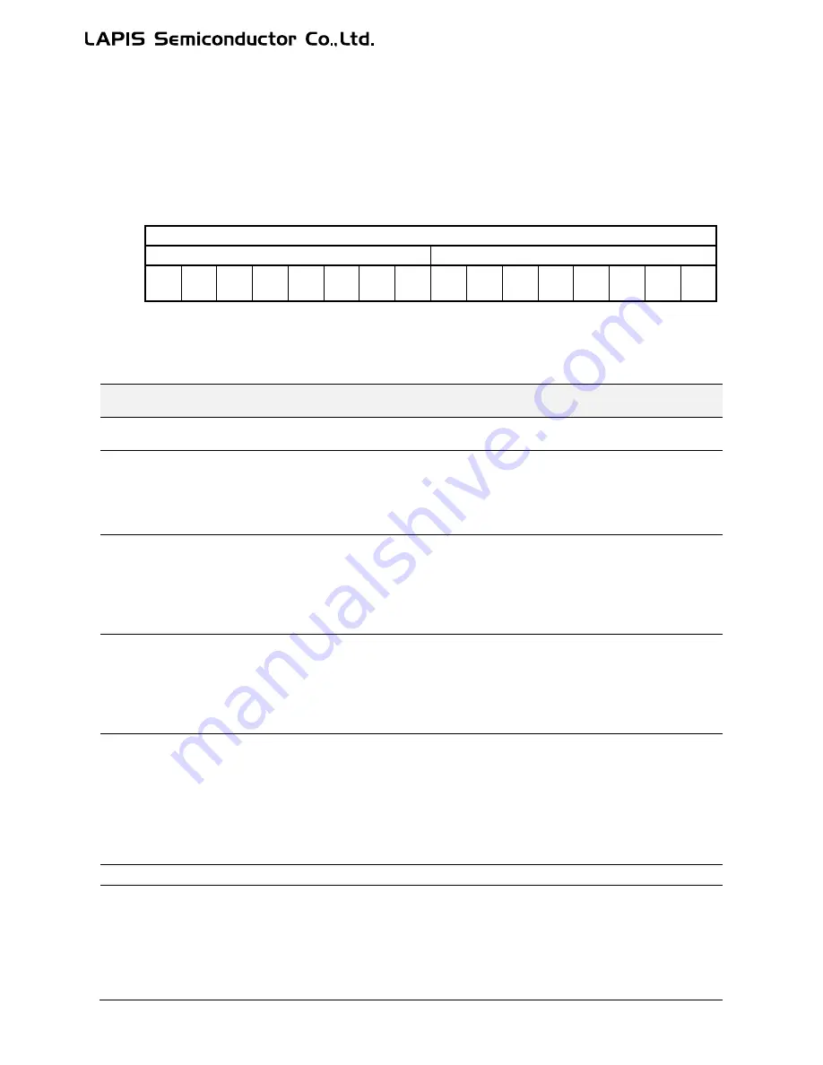
12.2.8 I
2
C Bus 0 Status Register (Master) (I2UM0STR)
I2UM0STR is a special function register (SFR) to indicate the state of the I
2
C bus unit in the master mode.
Address:
0xF6CC (I2UM0STA/I2UM0STR)
,
0xF6CD (I2UM0ISR)
Access:
R/W
Access size:
8/16bit
Initial value:
0x00
15
14
13
12
11
10
9
8
7
6
5
4
3
2
1
0
Word
I2UM0STR
Byte
I2UM0ISR
I2UM0STA
Bit
-
-
-
-
-
I2UM0
SPS
I2UM0
DS
I2UM0
AS
I2UM0
BO
-
-
-
-
I2UM0
ER
I2UM0
ACR
I2UM0
BB
R/W
R
R
R
R
R
R/W
R/W
R/W
R/W
R
R
R
R
R/W
R/W
R/W
Initial
value
0
0
0
0
0
0
0
0
0
0
0
0
0
0
0
0
Bit no.
Bit symbol
name
Description
15 to
11
-
Reserved bit
10
I2UM0SPS
This bit is used to indicate the usage state of the I
2
C bus in the master mode.
This bit is set to "1" when transmitting the stop condition has been completed on the I
2
C bus.
To reset this bit, write "1" to this bit or write "0" to I2UM0EN bit.
0: The stop condition has not been transmitted (Initial value)
1: The stop condition has been transmitted
9
I2UM0DS
This bit is used to indicate the usage state of the I
2
C bus in the master mode.
This bit is set to "1" when transmitting data or receiving data has been completed on the I
2
C
bus.
To reset this bit, write "1" to this bit or write "0" to I2UM0EN bit.
0: The transmission/reception has not been completed (Initial value)
1: The transmission/reception has been completed
8
I2UM0AS
This bit is used to indicate the usage state of the I
2
C bus in the master mode.
This bit is set to "1" when transmitting the start condition and 7 bit slave address have been
completed on the I
2
C bus.
To reset this bit, write "1" to this bit or write "0" to I2UM0EN bit.
0: The start condition and the slave address have not been transmitted (Initial value)
1: The start condition and the slave address have been transmitted
7
I2UM0BO
This bit is used to indicate the usage state of the I
2
C bus in the master mode.
This bit is set to "1" when transmitting the start condition has been completed and is reset to
“0” when the time (t
BUF
) has passed after transmitting the stop condition or there happened a
data communication error on the I2CU0_SDA pin.
When this bit is "1", it means the master has acquired use right of the I
2
C bus.
To reset this bit, write "1" to this bit or write "0" to I2UM0EN bit.
0: The use right of the I
2
C bus has not been acquired (Initial value)
1: The use right of the I
2
C bus has been acquired
6 to 3
-
Reserved bit
2
I2UM0ER
This bit is used to indicate a transmission error in the master mode.
When a bit of transmission data and the value on the I2CU0_SDA pin do not coincide, "1" is
set to this bit. To reset this bit, write "1" to this bit or write "0" to I2UM0EN bit.
0:
There was no transmission error (initial value)
1:
There was a transmission error
When this bit is set to "1" and the clock stretch function is used (I2UM0SYN = "1"), the
I2CU0_SDA pin output is disabled until the subsequent byte data communication terminates.
Summary of Contents for ML62Q1000 Series
Page 17: ...Chapter 1 Overview...
Page 112: ...Chapter 2 CPU and Memory Space...
Page 154: ...Chapter 3 Reset Function...
Page 166: ...Chapter 4 Power Management...
Page 196: ...Chapter 5 Interrupts...
Page 248: ...Chapter 6 Clock generation Circuit...
Page 274: ...Chapter 7 Low Speed Time Base Counter...
Page 291: ...Chapter 8 16 Bit Timer...
Page 320: ...Chapter 9 Functional Timer FTM...
Page 382: ...Chapter 10 Watchdog Timer...
Page 402: ...Chapter 11 Serial Communication Unit...
Page 456: ...Chapter 12 I2 C Bus Unit...
Page 491: ...Chapter 13 I2 C Master...
Page 512: ...Chapter 14 DMA Controller...
Page 531: ...Chapter 15 Buzzer...
Page 550: ...Chapter 16 Simplified RTC...
Page 559: ...Chapter 17 GPIO...
Page 594: ...Chapter 18 External Interrupt Function...
Page 612: ...Chapter 19 CRC Generator...
Page 632: ...Chapter 20 Analog Comparator...
Page 644: ...Chapter 21 D A Converter...
Page 655: ...Chapter 22 Voltage Level Supervisor...
Page 676: ...Chapter 23 Successive Approximation Type A D Converter...
Page 709: ...Chapter 24 Regulator...
Page 714: ...Chapter 25 Flash Memory...
Page 743: ...Chapter 26 Code Option...
Page 750: ...Chapter 27 LCD Driver...
Page 788: ...Chapter 28 On Chip Debug Function...
Page 795: ...Chapter 29 Safety Function...
Page 813: ...Appendix A...
Page 881: ...Revision History...