


ML62Q1000 Series User's Manual
Chapter 25 Flash Memory
FEUL62Q1000
25-16
25.3.2 Programming Program Memory Space
In the program memory space (flash memory), block erase in units of 16 Kbytes, sector erase in units of 1 Kbyte, and
reprogram in units of 4 bytes can be executed.
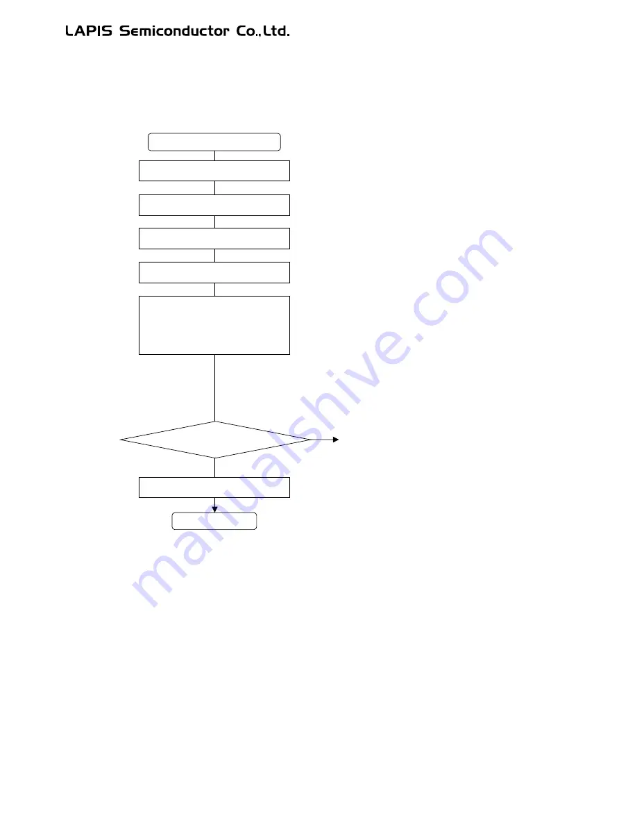
Figure 25-1 shows the flow diagram for erasing the program memory space.
Figure 25-1 Flow Diagram for Erasing Program Memory Space
[Note]
Ÿ
Only erase areas irrelevant to program processing. If erasing the area where program processing is in
progress, the LSI works incorrectly.
Ÿ
During block/sector erase, the CPU stops the operation for maximum 50 ms whereas peripheral circuits
continue operation. Therefore, clear the WDT counter accordingly.
Ÿ
For block/sector erase, place two NOP instructions following the instruction used to set FERS/FSERS
bits of the FLASHCON register to "1".
FSELF = 1
Start program memory erase
FLASHACP = 0xFA
FLASHACP = 0xF5
End
FLASHSEG = Segment address to be erased
FLASHA = Address to be erased
Enable flash programming
Flash acceptor setting
Flash address setting
Set the high-speed clock for the system clock through the
FCON register
System clock setting
FERS = 1 (block erase)/FSERS = 1 (sector erase)
__asm("NOP");
__asm("NOP");
Block/sector erase
Start flash memory erase
The CPU stops. It automatically starts operation again when the erase
is completed.
Continue programming?
YES
NO
FSELF = 0
Disable flash programming
Go to (1) in Figure 25-2
Summary of Contents for ML62Q1000 Series
Page 17: ...Chapter 1 Overview...
Page 112: ...Chapter 2 CPU and Memory Space...
Page 154: ...Chapter 3 Reset Function...
Page 166: ...Chapter 4 Power Management...
Page 196: ...Chapter 5 Interrupts...
Page 248: ...Chapter 6 Clock generation Circuit...
Page 274: ...Chapter 7 Low Speed Time Base Counter...
Page 291: ...Chapter 8 16 Bit Timer...
Page 320: ...Chapter 9 Functional Timer FTM...
Page 382: ...Chapter 10 Watchdog Timer...
Page 402: ...Chapter 11 Serial Communication Unit...
Page 456: ...Chapter 12 I2 C Bus Unit...
Page 491: ...Chapter 13 I2 C Master...
Page 512: ...Chapter 14 DMA Controller...
Page 531: ...Chapter 15 Buzzer...
Page 550: ...Chapter 16 Simplified RTC...
Page 559: ...Chapter 17 GPIO...
Page 594: ...Chapter 18 External Interrupt Function...
Page 612: ...Chapter 19 CRC Generator...
Page 632: ...Chapter 20 Analog Comparator...
Page 644: ...Chapter 21 D A Converter...
Page 655: ...Chapter 22 Voltage Level Supervisor...
Page 676: ...Chapter 23 Successive Approximation Type A D Converter...
Page 709: ...Chapter 24 Regulator...
Page 714: ...Chapter 25 Flash Memory...
Page 743: ...Chapter 26 Code Option...
Page 750: ...Chapter 27 LCD Driver...
Page 788: ...Chapter 28 On Chip Debug Function...
Page 795: ...Chapter 29 Safety Function...
Page 813: ...Appendix A...
Page 881: ...Revision History...