


ML62Q1000 Series User's Manual
Chapter 6
Clock Generation Circuit
FEUL62Q1000
6-1
6. Clock Generation Circuit
6.1 General Description
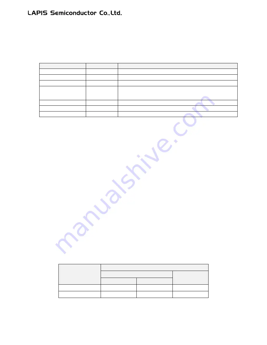
The clock generation circuit generates following kinds of clock and supplied them to the CPU or the peripheral circuits.
Table 6-1 Clocks generated by the clock generation circuit
Clock Name
Symbol
Description
Low-speed clock
LSCLK
Low speed clock for peripherals (32.768kHz)
Simplified RTC clock
*
1
RTCCLK
Low speed clock for the simplified RTC (32.768kHz)
High-speed clock
HSCLK
High speed clock for peripherals (Max. 24MHz)
System clock
SYSTEMCLK
CPU operating clock (32.768kHz or Max. 24MHz)
The maximum frequency depends on the CPU operation mode(See
Table 6-2)
Low-speed output clock
OUTLSCLK
Low speed output from a general port (32.768kHz)
High-speed output clock
OUTHSCLK
High speed output from an general port (Max. 12MHz)
WDT clock
WDTCLK
Clock for the watch dog timer (1.024kHz)
*
1
Available on the ML62Q1500 and ML62Q1700 group
For the output pins of OUTHSCLK and OUTLSCLK, see Chapter 17 "GPIO."
6.1.1 Features
•
Low-speed clock generation circuit
–
Low-speed RC oscillation circuit
–
Adjustable to ±1% by using the frequency adjustment function
–
A crysatl resonator is connectable*
1
–
In case the low-speed crystal oscillaion stopped, the clock is automatically switched to the low-speed RC
oscillation (clock backup function).
–
A low-speed external clock is available to input to XT1 pin
–
The crystal oscillation clock is continuously supplied during the reset input pin reset.
•
Simplified RTC clock*
1
–
Operating by the low-speed clock
•
High-speed oscillation circuit
–
PLL oscillation mode (16 MHz or 24 MHz is chooseable for the PLL reference frequency by the code option)
–
High-speed clock wake-up time is chooseable
•
WDT clock
–
RC1K oscillation circuit
–
The RC1K clock or the 1.024kHz divided from the low-speed RC oscillation clock is chooseable by the code
option.
*
1
Available on the ML62Q1500 and ML62Q1700 group
Table 6-2 shows relation of CPU operation mode and PLL oscillation reference frequency.
The CPU operation mode and the PLL oscillation reference frequency is chooseable by the code option. See Chapter 26
"Code Option" for more details.
Table 6-2 CPU operation mode and PLL oscillation reference frequency
PLL oscillation
reference frequency
Maximum operating frequency
SYSTEMCLK
HSCLK
Wait mode
No wait mode
24MHz
24MHz
6MHz
24MHz
16MHz
16MHz
8MHz
16MHz
Summary of Contents for ML62Q1000 Series
Page 17: ...Chapter 1 Overview...
Page 112: ...Chapter 2 CPU and Memory Space...
Page 154: ...Chapter 3 Reset Function...
Page 166: ...Chapter 4 Power Management...
Page 196: ...Chapter 5 Interrupts...
Page 248: ...Chapter 6 Clock generation Circuit...
Page 274: ...Chapter 7 Low Speed Time Base Counter...
Page 291: ...Chapter 8 16 Bit Timer...
Page 320: ...Chapter 9 Functional Timer FTM...
Page 382: ...Chapter 10 Watchdog Timer...
Page 402: ...Chapter 11 Serial Communication Unit...
Page 456: ...Chapter 12 I2 C Bus Unit...
Page 491: ...Chapter 13 I2 C Master...
Page 512: ...Chapter 14 DMA Controller...
Page 531: ...Chapter 15 Buzzer...
Page 550: ...Chapter 16 Simplified RTC...
Page 559: ...Chapter 17 GPIO...
Page 594: ...Chapter 18 External Interrupt Function...
Page 612: ...Chapter 19 CRC Generator...
Page 632: ...Chapter 20 Analog Comparator...
Page 644: ...Chapter 21 D A Converter...
Page 655: ...Chapter 22 Voltage Level Supervisor...
Page 676: ...Chapter 23 Successive Approximation Type A D Converter...
Page 709: ...Chapter 24 Regulator...
Page 714: ...Chapter 25 Flash Memory...
Page 743: ...Chapter 26 Code Option...
Page 750: ...Chapter 27 LCD Driver...
Page 788: ...Chapter 28 On Chip Debug Function...
Page 795: ...Chapter 29 Safety Function...
Page 813: ...Appendix A...
Page 881: ...Revision History...