


ML62Q1000 Series User's Manual
Chapter 9 Functional Timer (FTM)
FEUL62Q1000
9-55
9.3.7 Event Trigger/Emergency Stop Trigger Control
9.3.7.1 Trigger Signal
The functional timer can accept two types of trigger signal: event trigger and emergency stop trigger.
The event trigger is used as counter start/stop or trigger for capture.
The trigger source can be chosen from EXTRG0 to EXTRG7, CMP0D, TMH0TRG to TMH5TRG, or FTMnTRG.
The emergency stop trigger used to stop the timer operation, stops the counter and makes the Positive/Negative output
"L" level.
The trigger source can be chosen from EXTRG0, EXTRG4, and CMP0D.
The output of sampling controller is connected to EXTRG0 to EXTRG7. Sampling can be chosen using the port
controller register. In addition, the sampling controller is installed also in the functional timer. It can be set through
FTnTRF2 to FTnTRF0 bits of the FTnTRG1 register.
If EXTRG0 to EXTRG7 and CMP0D are chosen as the emergency stop trigger, sampling is not available on the
functional timer.
Use the external interrupt function and the sampling controller of the analogue comparator.
The interrupt sources of 16-bit timer and functional timer can be set through registers of each timer.
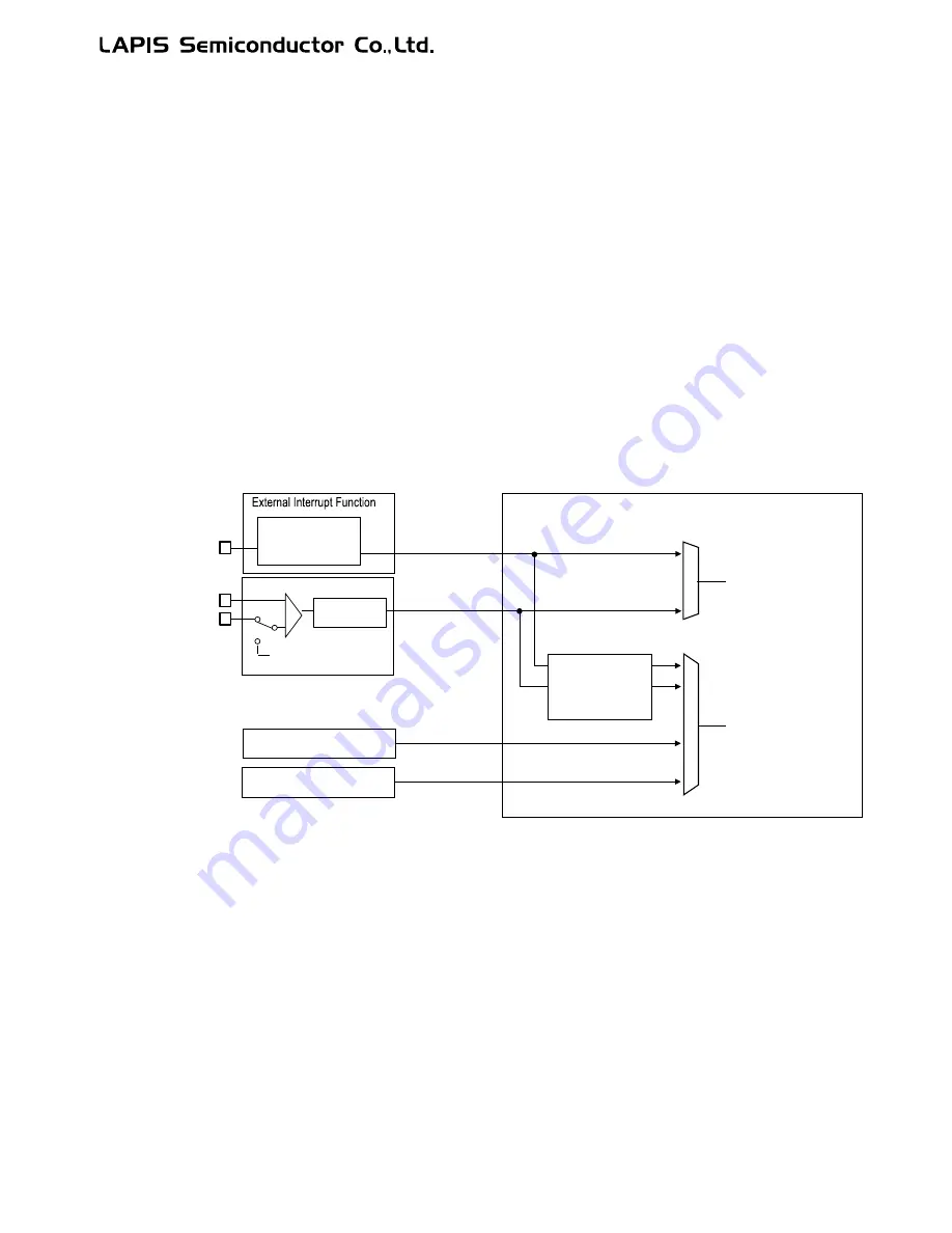
Figure 9-15 Input Path of Trigger Signal
TMHnTRG
FTMnTRG
Functional Timer (FTM)
Sampling
controller
16-bit timer n
Sampling with timer clock
Trigger for
emergency stop
Event trigger
for
starting/stopping
counter
CMP0D
EXTRGn
(n=0~7)
Analogue comparator
EXIn
(n=0~7)
CMP0P
+
-
Functional timer n
Sampling
controller
Sampling
controller
Internal reference
voltage (0.8 V)
CMP0M
EXTRG0, EXTRG4
Summary of Contents for ML62Q1000 Series
Page 17: ...Chapter 1 Overview...
Page 112: ...Chapter 2 CPU and Memory Space...
Page 154: ...Chapter 3 Reset Function...
Page 166: ...Chapter 4 Power Management...
Page 196: ...Chapter 5 Interrupts...
Page 248: ...Chapter 6 Clock generation Circuit...
Page 274: ...Chapter 7 Low Speed Time Base Counter...
Page 291: ...Chapter 8 16 Bit Timer...
Page 320: ...Chapter 9 Functional Timer FTM...
Page 382: ...Chapter 10 Watchdog Timer...
Page 402: ...Chapter 11 Serial Communication Unit...
Page 456: ...Chapter 12 I2 C Bus Unit...
Page 491: ...Chapter 13 I2 C Master...
Page 512: ...Chapter 14 DMA Controller...
Page 531: ...Chapter 15 Buzzer...
Page 550: ...Chapter 16 Simplified RTC...
Page 559: ...Chapter 17 GPIO...
Page 594: ...Chapter 18 External Interrupt Function...
Page 612: ...Chapter 19 CRC Generator...
Page 632: ...Chapter 20 Analog Comparator...
Page 644: ...Chapter 21 D A Converter...
Page 655: ...Chapter 22 Voltage Level Supervisor...
Page 676: ...Chapter 23 Successive Approximation Type A D Converter...
Page 709: ...Chapter 24 Regulator...
Page 714: ...Chapter 25 Flash Memory...
Page 743: ...Chapter 26 Code Option...
Page 750: ...Chapter 27 LCD Driver...
Page 788: ...Chapter 28 On Chip Debug Function...
Page 795: ...Chapter 29 Safety Function...
Page 813: ...Appendix A...
Page 881: ...Revision History...