Rostock MAX v2 Assembly Guide
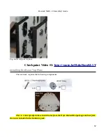
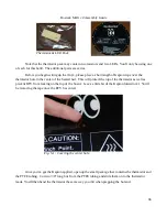
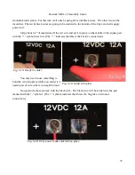
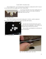
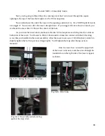
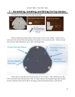
The mounting plate has a pair of notches that are designed to accommodate the LED. You need
to orient that feature so that it points to the “front” of the machine.
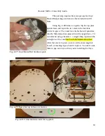
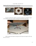
Lay the Onyx heated bed on top of the mounting plate and
rotate it so the LED is at the front. (The LED will be directly
opposite the Z tower in the rear.)
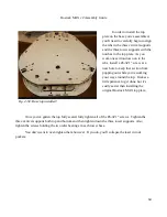
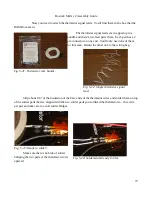
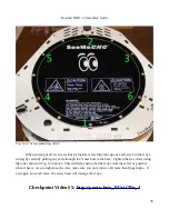
Now it's time to attach the Onyx and its mounting plate to the base – grab the round nylon
spacers and the six #4-40 flat head screws that were included with the Onyx.
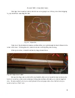
Turn the Onyx so that the first hole lines up with
the first hole in the mounting plate. (The first hole is the
one between the two LED clearance notches.)
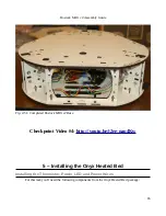
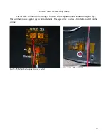
Slide a #4-40 screw through the Onyx & mount and
slip on a nylon spacer.
76
Fig. 5-28: LED notches.
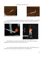
Fig. 5-29: Nylon spacers.
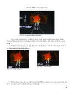
Fig. 5-30: Screw & nylon spacer on #1 hole.
Содержание Rostock MAX v2
Страница 25: ...Rostock MAX v2 Assembly Guide Melamine Parts Sheet 1 25 ...
Страница 26: ...Rostock MAX v2 Assembly Guide Melamine Parts Sheet 2 Melamine Parts Sheet 3 26 ...
Страница 27: ...Rostock MAX v2 Assembly Guide Melamine Parts Sheet 4 27 ...
Страница 171: ...Rostock MAX v2 Assembly Guide 171 Fig 14 8 Spool holder support installed ...

