Rostock MAX v2 Assembly Guide
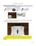
Note that these u-joint carriers are an interim design and are simply the original v1 parts that
have had the end posts ground off. You may find that the grinding has removed enough material that
the alignment pin is no longer able to remain in place. If you find that happening, just remove that
alignment pin and hold it in place until you can get the socket head cap screws installed.
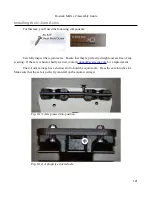
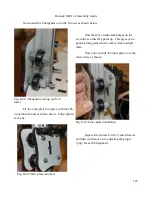
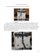
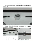
From the front side of the U-Joint carriage, insert two #6-32, 5/8” socket head cap screws
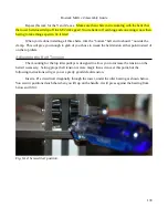
through the holes indicated. Install two #6-32 Nylon lock nuts on the back and tighten them down
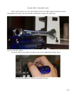
using a 7/64” hex wrench and a 5/16” wrench.
119
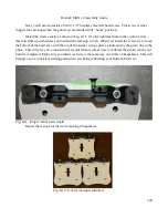
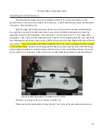
Fig. 8-7: U-Joint carriage fitted properly.
Fig. 8-8: SHCS inserted...
Fig. 8-9: Nylon lock nut installed.
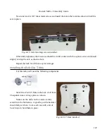
Fig. 8-10: Both SHCS installed.
Содержание Rostock MAX v2
Страница 25: ...Rostock MAX v2 Assembly Guide Melamine Parts Sheet 1 25 ...
Страница 26: ...Rostock MAX v2 Assembly Guide Melamine Parts Sheet 2 Melamine Parts Sheet 3 26 ...
Страница 27: ...Rostock MAX v2 Assembly Guide Melamine Parts Sheet 4 27 ...
Страница 171: ...Rostock MAX v2 Assembly Guide 171 Fig 14 8 Spool holder support installed ...

