Rostock MAX v2 Assembly Guide
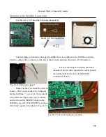
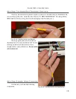
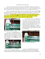
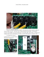
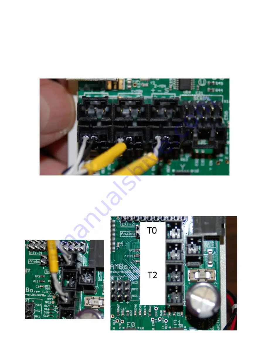
Now you can install the thermistor connectors. Remember how I had you label the thermistor
leads with “
T0
” and “
T2
”? Well there was a method to that particular madness. The thermistor
positions on the RAMBo are marked T0 through T3. By labeling them ahead of time, it eliminates any
confusion about which is which and you won't have to refer to the manual to see who does what. :)
I've marked the T0 and T2
positions for you, so go ahead and get
the thermistors plugged in!
193
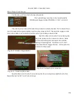
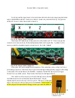
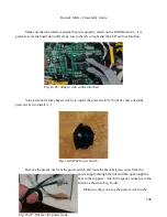
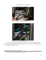
Fig. 16-31: End stops plugged in.
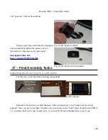
Fig. 16-32: Thermistor connectors.
Fig. 16-33: Thermistors plugged in.
Содержание Rostock MAX v2
Страница 25: ...Rostock MAX v2 Assembly Guide Melamine Parts Sheet 1 25 ...
Страница 26: ...Rostock MAX v2 Assembly Guide Melamine Parts Sheet 2 Melamine Parts Sheet 3 26 ...
Страница 27: ...Rostock MAX v2 Assembly Guide Melamine Parts Sheet 4 27 ...
Страница 171: ...Rostock MAX v2 Assembly Guide 171 Fig 14 8 Spool holder support installed ...

