Rostock MAX v2 Assembly Guide
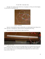
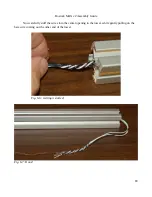
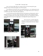
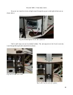
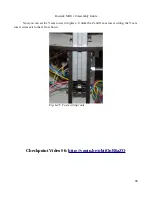
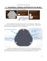
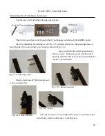
Now remove the bare wire and set it aside – we'll use it again next, but first you need to identify
and mark each pair of the end stop wires.
You can easily identify which wire is which by gently pulling on one end and observing which
wire moves. When you think you've identified a wire, grab the other end and see if pulling it back and
forth through the tower works as you expect it to – you should feel yourself pulling the wire from either
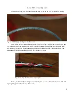
end. Once you've identified your first black & white pair, write an “X” on the spade connector using a
Sharpie or other indelible marker. At the opposite end, twist the wires together about 1/4” from the end
of the crimp on connector and label it.
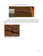
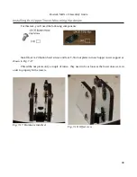
When you've got both ends marked, tie a very loose
knot in the top pair as shown to the right. Repeat this
identification and labeling process for the other two end stop
wire pairs. You'll mark the second as the “Y” axis and the third
as the “Z” axis.
84
Fig. 6-7: X Axis end stop wires labeled.
Fig. 6-8: End stop wires paired.
Содержание Rostock MAX v2
Страница 25: ...Rostock MAX v2 Assembly Guide Melamine Parts Sheet 1 25 ...
Страница 26: ...Rostock MAX v2 Assembly Guide Melamine Parts Sheet 2 Melamine Parts Sheet 3 26 ...
Страница 27: ...Rostock MAX v2 Assembly Guide Melamine Parts Sheet 4 27 ...
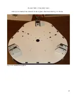
Страница 171: ...Rostock MAX v2 Assembly Guide 171 Fig 14 8 Spool holder support installed ...


