Rostock MAX v2 Assembly Guide
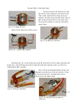
Now strip off about 3/8” from the two 18ga
black & red wires coming out of the hot end loom.
These will be attached to the crimps you've just
installed. Note that it doesn't matter which side you
pick for black and which for red. Resistors don't
have a specific polarity, so connection orientation
doesn't matter.
Repeat for the other side with the red wire.
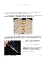
Bend the leads “up” or towards the open end of the hot end and cover the crimp connectors with
Kapton tape. This will help prevent short circuits that could at the least blow fuses or at the worst,
damage the RAMBo controller.
Now you'll be attaching the thermistor leads to the
18ga green and white wires in the hot end loom. Please
be careful with this task – the thermistor wires are
delicate and can be broken easily.
153
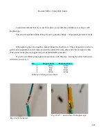
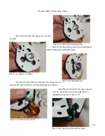
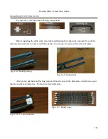
Fig. 11-15: Ready for wires.
Fig. 11-16: Black wire attached.
Fig. 11-17: ...and red wire attached.
Fig. 11-18: Kapton insulation.
Fig. 11-19: Thermistor lead soldered to
white wire.
Содержание Rostock MAX v2
Страница 25: ...Rostock MAX v2 Assembly Guide Melamine Parts Sheet 1 25 ...
Страница 26: ...Rostock MAX v2 Assembly Guide Melamine Parts Sheet 2 Melamine Parts Sheet 3 26 ...
Страница 27: ...Rostock MAX v2 Assembly Guide Melamine Parts Sheet 4 27 ...
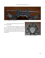
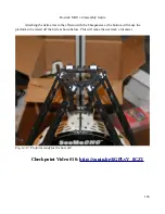
Страница 171: ...Rostock MAX v2 Assembly Guide 171 Fig 14 8 Spool holder support installed ...


