


Rostock MAX v2 Assembly Guide
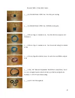
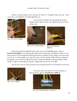
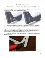
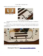
Cut the connector off, flush with the wires – this gives you the most wire to work with. When
you're done, bundle them up and set them aside.
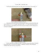
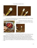
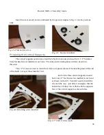
The RAMBo board needs two additional pair of
yellow & black wires – we'll get those from the connector
shown below.
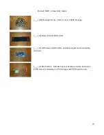
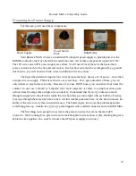
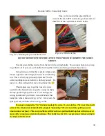
A few concerned builders have written me about the connectors (or lack of) that I show on this
page and the next. The important parts are the yellow and black wires. It doesn't really matter
WHERE you get them, so long as the wires you choose are long enough to do the job. How long is
“long enough”? Well grab the bundle with the 8 pin connector on that and use that as the “base”
length. If you don't have the 8 pin connector, find the longest yellow & black wire set on the power
supply, match to the next longest, etc. Do this until you have the 6 black & yellow wires needed for the
build.
35
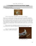
Fig. 3-15A: 8 pin connector.
Fig. 3-15B: 8 pin connector, split.
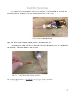
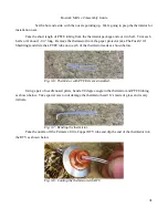
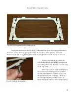
Fig. 3-16: Heated bed power wires.
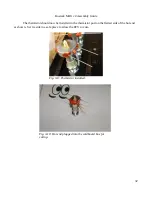
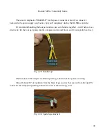
Fig. 3-17: Additional wires..
Содержание Rostock MAX v2
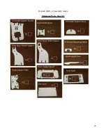
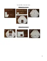
Страница 25: ...Rostock MAX v2 Assembly Guide Melamine Parts Sheet 1 25 ...
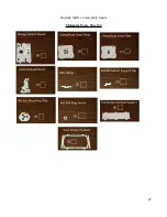
Страница 26: ...Rostock MAX v2 Assembly Guide Melamine Parts Sheet 2 Melamine Parts Sheet 3 26 ...
Страница 27: ...Rostock MAX v2 Assembly Guide Melamine Parts Sheet 4 27 ...
Страница 171: ...Rostock MAX v2 Assembly Guide 171 Fig 14 8 Spool holder support installed ...