


Rostock MAX v2 Assembly Guide
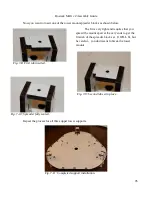
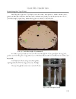
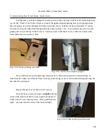
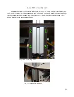
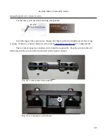
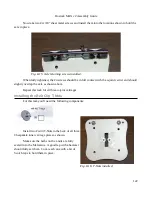
Now we need to get the wires tied down! The axis tie locations consist of two small laser cut
slots in the right side of each upper tower mount. A representative example is shown below in Fig. 7-
38. You will want to temporarily remove the idler pulley in order to give yourself more room to work.
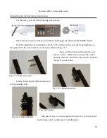
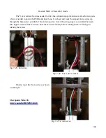
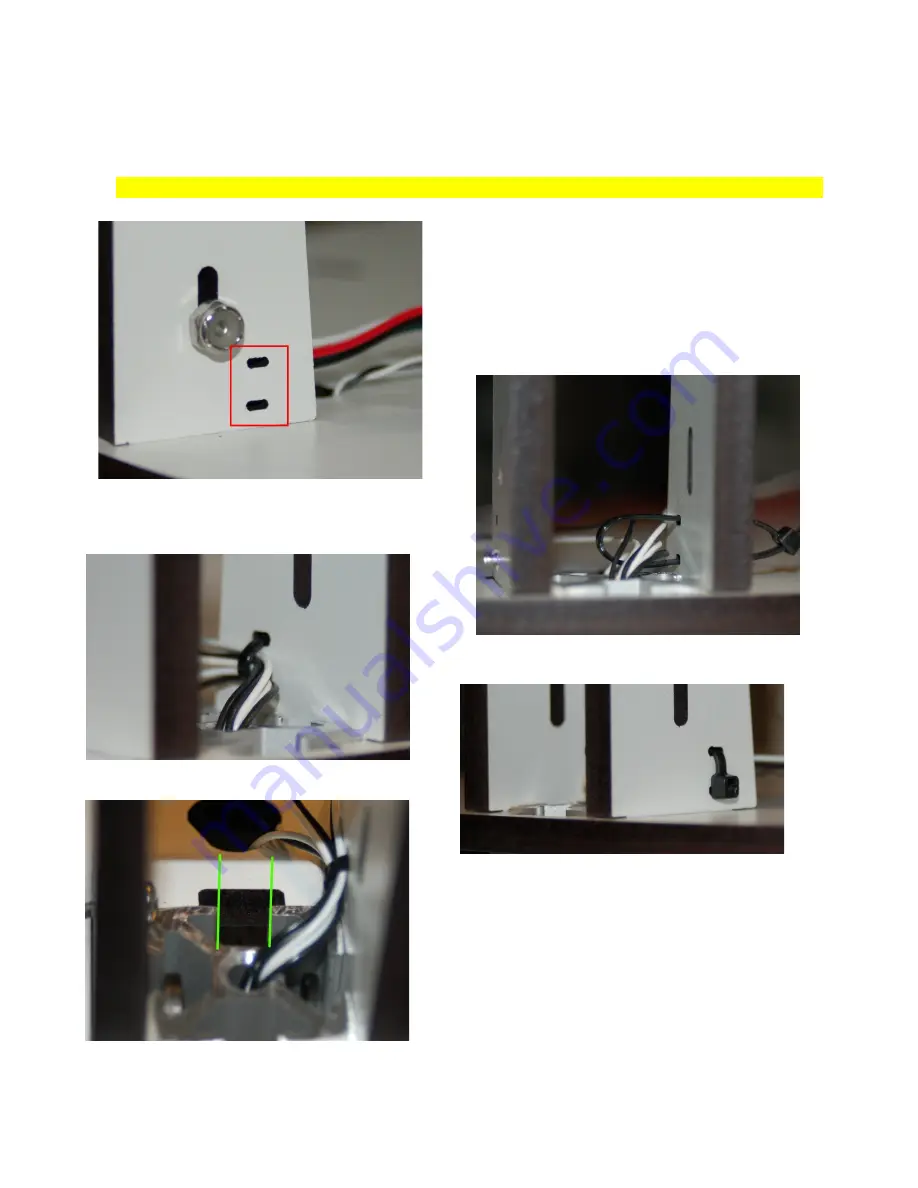
Let's start with the X axis. Make sure that the end
stop wires exit the top of the tower to the right – when
the wires are pulled tight using the wire tie, it will keep
them from interfering with the belt path.
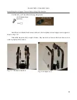
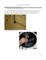
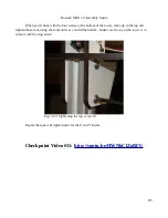
When you're done, re-install the idler pulley if you
removed it, and we'll move on to tying down the end stop
wires between the X and Z towers.
109
Fig. 7-38: Example tie down point.
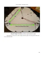
Fig. 7-39: Capturing the end stop wires.
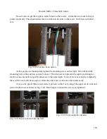
Fig. 7-40: End stop wires pulled tight.
Fig. 7-41: Tail clipped off.
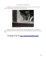
Fig. 7-42: Clear belt path.
Содержание Rostock MAX v2
Страница 25: ...Rostock MAX v2 Assembly Guide Melamine Parts Sheet 1 25 ...
Страница 26: ...Rostock MAX v2 Assembly Guide Melamine Parts Sheet 2 Melamine Parts Sheet 3 26 ...
Страница 27: ...Rostock MAX v2 Assembly Guide Melamine Parts Sheet 4 27 ...
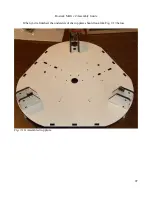
Страница 171: ...Rostock MAX v2 Assembly Guide 171 Fig 14 8 Spool holder support installed ...