Rostock MAX v2 Assembly Guide
Mounting the RAMBo Controller
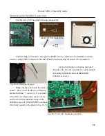
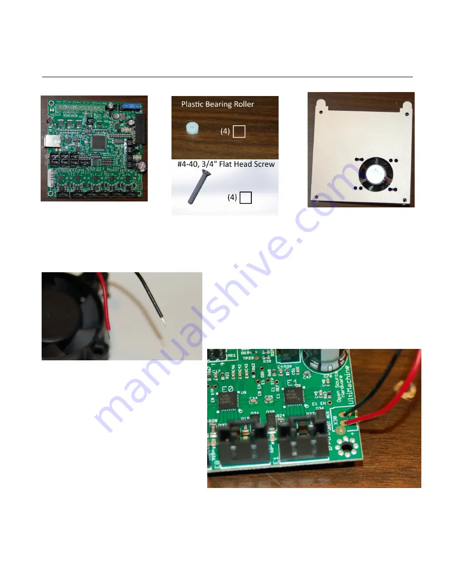
For this task, you'll need the following components:
The first thing you'll need to do is get the 40MM fan wires soldered to the RAMBo controller.
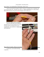
Start by cutting off the connector at the end of the fan leads and strip off about 1/8” of insulation.
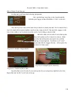
Get your soldering iron heating and insert
the ends of the fan wires into the two solder pads on
the bottom right hand corner of the RAMBo
controller as shown.
Make sure that you install the wires as
shown – the red wire needs to be in the pad
marked with the “+” next to it. If you install
it the other way, the fan may run in reverse
and won't cool the MOSFET chips on the
RAMBo very well. (The MOSFETs are those
little black squares in the photo in Fig. 16-7.)
184
Fig. 16-6: Fan leads stripped.
Fig. 16-7: Fan wire installation location.
Содержание Rostock MAX v2
Страница 25: ...Rostock MAX v2 Assembly Guide Melamine Parts Sheet 1 25 ...
Страница 26: ...Rostock MAX v2 Assembly Guide Melamine Parts Sheet 2 Melamine Parts Sheet 3 26 ...
Страница 27: ...Rostock MAX v2 Assembly Guide Melamine Parts Sheet 4 27 ...
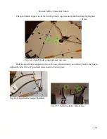
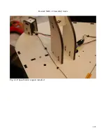
Страница 171: ...Rostock MAX v2 Assembly Guide 171 Fig 14 8 Spool holder support installed ...

