Rostock MAX v2 Assembly Guide
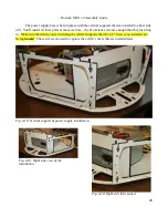
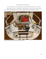
The Z axis (in the back of the machine) tower & motor support installs the same way as the
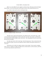
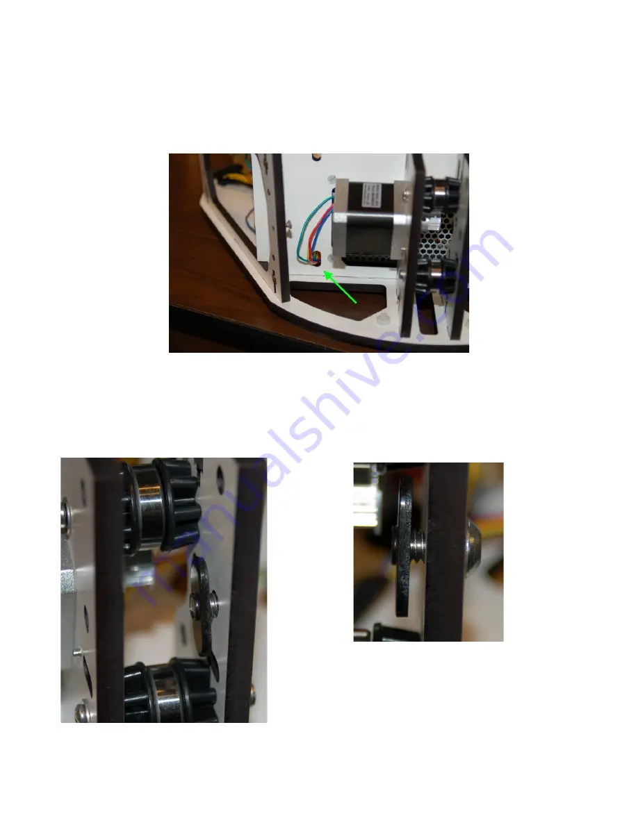
other two. The wires for the Z axis stepper motor should be routed through the lower hole in the power
supply bracket as shown below. The connector is a tight squeeze, but it WILL fit.
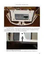
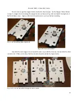
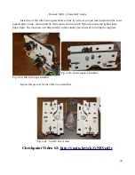
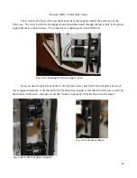
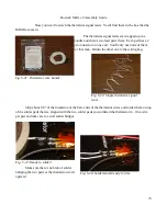
Now you need to install four of the ¼-20 cap head screws and four T-Slot nut plates into each
tower support assembly. Only thread the T-Slot nut plates enough to feel the end of the screw catch all
the threads in the plate – the space is needed in order to properly fit inside the slot in the tower.
61
Fig. 4-43: Routing the Z axis stepper wires.
Fig. 4-44: T-Slot nut plate installed.
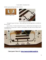
Fig. 4-45: Depth example.
Содержание Rostock MAX v2
Страница 25: ...Rostock MAX v2 Assembly Guide Melamine Parts Sheet 1 25 ...
Страница 26: ...Rostock MAX v2 Assembly Guide Melamine Parts Sheet 2 Melamine Parts Sheet 3 26 ...
Страница 27: ...Rostock MAX v2 Assembly Guide Melamine Parts Sheet 4 27 ...
Страница 171: ...Rostock MAX v2 Assembly Guide 171 Fig 14 8 Spool holder support installed ...


