Rostock MAX v2 Assembly Guide
from the wiring loom as shown below. Take care to
ensure that you don't accidentally
pinch the power
wires between the top of the fan shroud and the
bottom surface of the hot end
mount!
Don't forget to cover your soldered joints with Kapton!
Now re-install the arms on to the effector platform.
Don't forget to make sure that the u-joints are installed
with the ejector pin marks facing
away
from the effector
platform!
The PEEK fan shroud is “virtually” linked
255
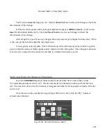
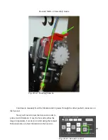
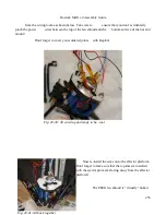
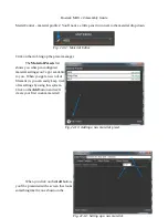
Fig. 20-30: All wired up and ready to be...cool.
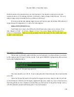
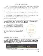
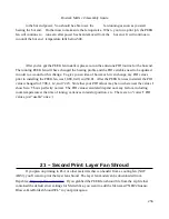
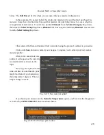
Fig. 20-31: All back together.
Содержание Rostock MAX v2
Страница 25: ...Rostock MAX v2 Assembly Guide Melamine Parts Sheet 1 25 ...
Страница 26: ...Rostock MAX v2 Assembly Guide Melamine Parts Sheet 2 Melamine Parts Sheet 3 26 ...
Страница 27: ...Rostock MAX v2 Assembly Guide Melamine Parts Sheet 4 27 ...
Страница 171: ...Rostock MAX v2 Assembly Guide 171 Fig 14 8 Spool holder support installed ...

