Rostock MAX v2 Assembly Guide
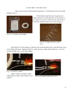
Now you need to attach the thermistor signal leads. You'll find them in the box that the
RAMBo came in.
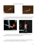
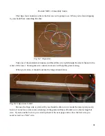
The thermistor signal leads are wrapped up in a
bundle and there's two lead pairs there. Each pair has a 2
pin connector on one end. You'll only need one of them
for this task. Return the other one to the wiring bag.
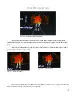
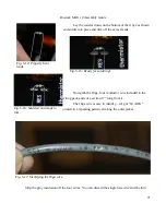
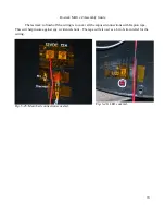
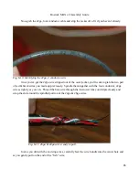
Strip about 1/8” of the insulation of the bare ends of the thermistor wires and solder them on top
of the solder pads that are aligned with the two solder pads you soldered the thermistor to. One wire
per pad and take care to avoid solder bridges.
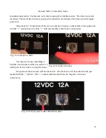
Make sure there's no blob of solder
bridging the two pads or the thermistor won't
operate!
73
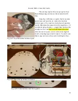
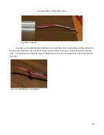
Fig. 5-21: Thermistor wire bundle.
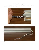
Fig. 5-22: Single thermistor signal
lead.
Fig. 5-23: Ready to solder!
Fig. 5-24: Soldered and ready to trim.
Содержание Rostock MAX v2
Страница 25: ...Rostock MAX v2 Assembly Guide Melamine Parts Sheet 1 25 ...
Страница 26: ...Rostock MAX v2 Assembly Guide Melamine Parts Sheet 2 Melamine Parts Sheet 3 26 ...
Страница 27: ...Rostock MAX v2 Assembly Guide Melamine Parts Sheet 4 27 ...
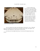
Страница 171: ...Rostock MAX v2 Assembly Guide 171 Fig 14 8 Spool holder support installed ...

