Rostock MAX v2 Assembly Guide
Wire Prep: End Stops
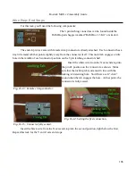
For this task, you'll need the following components:
The 3 pin latching connectors can be found inside the
RAMBo parts baggie (marked “RAMBo v1.3 Kit” or similar).
The end stop wires came with female crimp connectors already attached. Each connector has a
tiny little metal tab that points slightly away from the connector itself. This metal tab engages a little
hole in the middle of each connector position on the 3 pin latching connector shell.
Insert the white wire from the X axis end stop into
the pin #1 position on the connector as shown. Make
sure that the locking tab is oriented in line with the
locking tab retaining hole. You'll hear a soft “click”
sound when the tab engages the hole. At that point, the
connector is fully seated.
Insert the black wire from the X axis end stop into the second position, right below the first.
Repeat this task for the Y and Z axis end stops.
186
Fig. 16-13: Female crimp connector.
Fig. 16-14: Setting the first connection.
Fig. 16-15: Connector fully seated.
Содержание Rostock MAX v2
Страница 25: ...Rostock MAX v2 Assembly Guide Melamine Parts Sheet 1 25 ...
Страница 26: ...Rostock MAX v2 Assembly Guide Melamine Parts Sheet 2 Melamine Parts Sheet 3 26 ...
Страница 27: ...Rostock MAX v2 Assembly Guide Melamine Parts Sheet 4 27 ...
Страница 171: ...Rostock MAX v2 Assembly Guide 171 Fig 14 8 Spool holder support installed ...

