Rostock MAX v2 Assembly Guide
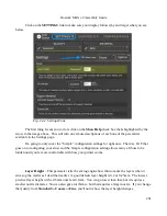
Here's what the
Coarse
,
Standard
, and
Fine
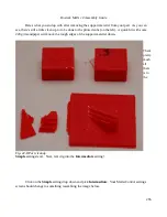
layer heights look like when printing the little test
cube in ABS plastic.
Starting from left to right, the layer heights are 0.1mm, 0.2mm and 0.3mm. You'll notice that
the top layer on the 0.1mm print is kind of ratty and torn up. This is because the number of top layers
is set to 3. This is perfectly ok with thicker layer heights, but it should have been set to at least 5 for the
0.1mm layer height that the
Fine
setting uses. You'll learn how to tweak that in a little bit.
You can see how the smoothness of the sides decrease as the layer thickness increases. If you
want to print something really quick, you could go up to a 0.35mm layer height. I wouldn't recommend
anything over 0.40mm if you're using a 0.5mm nozzle however.
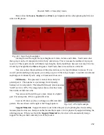
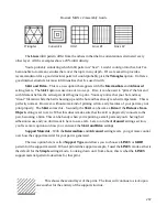
Fill Density
– This parameter controls how solid your
printed part is. The number is a percentage, from 0 (totally
hollow) to 1 (totally solid). The default fill density (also known as
“infill”) is 0.2 or 20%. The image below shows what that looks
like inside our little test cube.
You can tweak the infill to get a more robust or a lighter
part. For most prints, 20% is a good infill value.
Later on I'll show you how to change to a different infill
pattern. The one shown on the right is the Triangle pattern.
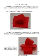
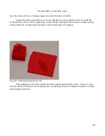
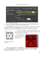
Support Material
– Support material is used when the part you're printing has free-standing
features (like the chin on a bust) or another feature that requires it to be physically supported during the
printing process. When you check the
Support Material
box, the slicer will automatically design
support for the part that's currently (or will be) loaded.
262
Fig. 22-3: Layer height examples.
Fig. 22-4: 20% infill example.
Содержание Rostock MAX v2
Страница 25: ...Rostock MAX v2 Assembly Guide Melamine Parts Sheet 1 25 ...
Страница 26: ...Rostock MAX v2 Assembly Guide Melamine Parts Sheet 2 Melamine Parts Sheet 3 26 ...
Страница 27: ...Rostock MAX v2 Assembly Guide Melamine Parts Sheet 4 27 ...
Страница 171: ...Rostock MAX v2 Assembly Guide 171 Fig 14 8 Spool holder support installed ...


