


Rostock MAX v2 Assembly Guide
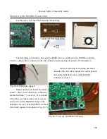
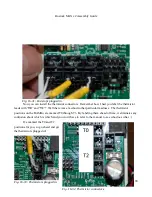
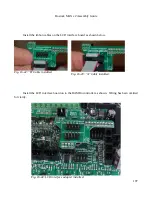
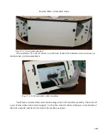
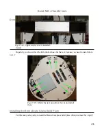
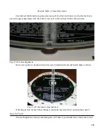
Install the ribbon cables on the LCD interface board as shown below.
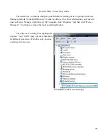
Install the LCD interface board on to the RAMBo controller as shown. Wiring has been omitted
for clarity.
197
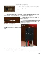
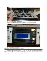
Fig. 16-44:LCD interface adapter installed.
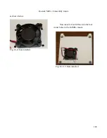
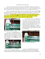
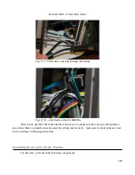
Fig. 16-42: "B" Cable installed.
Fig. 16-43: "A" Cable installed.
Содержание Rostock MAX v2
Страница 25: ...Rostock MAX v2 Assembly Guide Melamine Parts Sheet 1 25 ...
Страница 26: ...Rostock MAX v2 Assembly Guide Melamine Parts Sheet 2 Melamine Parts Sheet 3 26 ...
Страница 27: ...Rostock MAX v2 Assembly Guide Melamine Parts Sheet 4 27 ...
Страница 171: ...Rostock MAX v2 Assembly Guide 171 Fig 14 8 Spool holder support installed ...