Rostock MAX v2 Assembly Guide
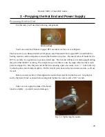
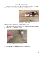
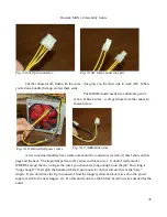
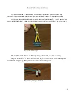
Grab the four-pair bundle of wires and strip off about 1/2” of insulation from each wire. When
you're done, you should have all eight stripped like so:
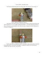
Now take the four black wires and spindle them into a
bundle as shown below in Fig. 3-24. Repeat that process for the
yellow wires.
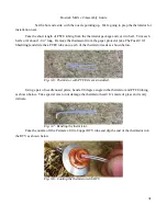
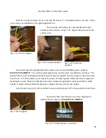
Now you'll insert the bundled black & yellow wires into the RAMBo power connector
EXACTLY AS SHOWN
. The terminal posts tighten down with a small, flat bladed screwdriver. The
terminal block could be shipped with them opened, but you should check by trying to loosen the screw
in each one. If it clicks softly as you loosen the screw, it's fully opened. Make sure they're tight after
inserting the wires! Make sure that there's no stray strands escaping the terminal position for either
bundle. A single strand could short the power supply and cause you no end of grief.
Grab the last two pair of yellow & black wires and strip about 3/8” of insulation from each one.
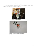
Now insert these last four wires into the compression
terminal block connector
EXACTLY AS SHOWN.
38
Fig. 3-23: Wires stripped.
Fig. 3-24: Grounds bundled.
Fig. 3-25: Primaries
bundled.
Fig. 3-26: Stripped!
Fig. 3-27: Finished power connector.
Содержание Rostock MAX v2
Страница 25: ...Rostock MAX v2 Assembly Guide Melamine Parts Sheet 1 25 ...
Страница 26: ...Rostock MAX v2 Assembly Guide Melamine Parts Sheet 2 Melamine Parts Sheet 3 26 ...
Страница 27: ...Rostock MAX v2 Assembly Guide Melamine Parts Sheet 4 27 ...
Страница 171: ...Rostock MAX v2 Assembly Guide 171 Fig 14 8 Spool holder support installed ...

