Rostock MAX v2 Assembly Guide
The 4 pin latching connector and crimp sockets are found
inside R
AMBo parts baggie (marked “RAMBo v1.3 Kit” or
similar).
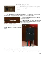
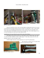
This task requires that you crimp four crimp sockets on to the leads coming out of the Y tower
from the extruder. Please refer to the notes about wire crimping in the Introduction.
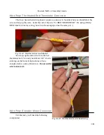
Crimp a female socket on to each of the four 22ga
extruder extension wires.
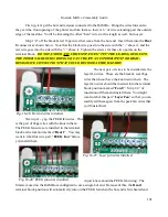
The 4 pin latching connector body has an arrow that
marks the #1 pin (the same marking as the one you saw
on the thermistor connector).
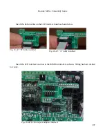
Insert the wires into the connector shell in
the order shown in Fig. 16-25. (green, red, black,
white)
Wiring the RAMBo Controller – Terminal Block
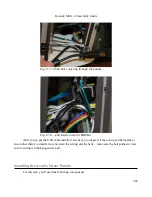
Note that all wiring should be brought through the center opening in the front vertical support!
190
Fig. 16-24: First of four crimps.
Fig. 16-25: Connector wire order.
Содержание Rostock MAX v2
Страница 25: ...Rostock MAX v2 Assembly Guide Melamine Parts Sheet 1 25 ...
Страница 26: ...Rostock MAX v2 Assembly Guide Melamine Parts Sheet 2 Melamine Parts Sheet 3 26 ...
Страница 27: ...Rostock MAX v2 Assembly Guide Melamine Parts Sheet 4 27 ...
Страница 171: ...Rostock MAX v2 Assembly Guide 171 Fig 14 8 Spool holder support installed ...

